
Nexus Manual

32
8. Each control board has an integral auto-reset fuse. If the
current exceeds 1.8 amps the fuse will open, interrupting
the ow of electric current to the control board. This will
immediately turn off the unit. Once the current or voltage
is reduced to acceptable levels, the temperature will
decrease and the fuse will automatically reset.
9. The high limit switch interrupts the ow of electrical
current to the ignition control and gas valve,
interrupting the ow of gas to the gas burner if the
unit heater becomes overheated.
10. The rollout switch interrupts the flow of the electrical
current to the ignition control and gas valve, interrupting
the ow of gas to the gas burner if the temperature of the
burner compartment exceeds rollout set point. If the rollout
switch trips, the combustion, inducer and supply fans will
continue to run until the rollout switch is manually reset.
11. The ue temperature limit interrupts the ow of electric
current to the ignition control and gas valve, interrupting
the ow of gas to the gas burner if the ue temperature
exceeds ue temp limit.
12. Once the thermostat is satised, or the high limit, ue
temperature limit, or condensate oat switch interrupts
the ow of electric current to the control board, the unit
will begin a post-purge period. When the post-purge
period ends, the propeller fan, combustion blower and
power venter motor are de-energized.
13. The wall thermostat, supplied optionally, is a temperature
sensitive switch that operates the vent and ignition
system to control the temperature of the space being
heated. The thermostat must be mounted on a vertical,
vibration-free surface free from air currents and in
accordance with the furnished instructions (see also
the ELECTRICAL CONNECTIONS section).
START-UP (Also refer to lighting instruction plate
equipped on the unit)
1. Open the manual gas valve in the gas supply line to
the unit heater. Loosen the union in the gas line to
purge it of air. Tighten the union and check for leaks.
Never use an open ame to detect
gas leaks. Explosive conditions may exist which
could result in personal injury or death.
2. Open the manual valve on the unit heater.
3. Set control mode DIP switches #1-5 to OFF. Discon-
nect 2-10 VDC wires, if applicable.
4. Turn ON the electrical power.
5. The unit should be under the control of the thermostat.
Place a jumper between R and W1 and determine
that the combustion blower and power venter motors
start beginning pre-purge. After 30-35 seconds, the
orange ignition LED should be ashing (on the control
board located in the control box), burners will ignite
and unit will run at this ignition period for one minute.
The orange ignition LED will become solid.
6. Set (Run %) potentiometer to 100% on the control board
to force the unit to high re. Turn clockwise (100).
OPERATION – HIGH EFFICIENCY PROPELLER UNITS DIRECT SPARK IGNITION
(continued)
7. It may take a few minutes for the unit to modulate, but
once in high re, measure the supply gas pressure and
record. Supply gas pressure should be 5.0 to 14.0" W.C.
for natural gas, 8.0 to 14.0" W.C. for propane (LP) gas.
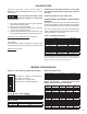
8. Place a combustion analyzer in the ue pipe. Carbon
dioxide (CO
2
) should be within the range shown in Table
10. Carbon monoxide (CO) values will vary depending
on ue pipe length, but CO should always be below
100 PPM. If CO/CO
2
values are not within the given
range:
a. For unit sizes 50/200, adjust high re adjustment
on gas valve until it is within range. Adjustments
should be made with small increments, a quarter
(1/4) turn at a time. Clockwise rotation decreases
input, counter clockwise increases input.
b. For unit sizes 300/400, turn the trim valve stem
until it is within range using an adjustable wrench.
Asjustments should be made in small increments,
an eighth (1/8) turn at a time. Clockwise rotation
decreases input, counter clockwise rotation
increases input.
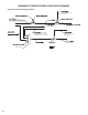
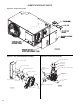
NOTE: See Figures 22A and 22B for gas valve and trim
valve adjustment locations.
9. Turn the (Run %) potentiometer counter clockwise
(33) to force the unit to low re.
10. Measure CO/CO
2
using a combustion analyzer. CO
2
should be within the range shown in Table 10. CO values
will vary depending on ue pipe length, but CO should
always be below 100 PPM. If CO/CO
2
values are not
within the given range:
a. For unit sizes 50/200, adjust low re adjustment
on gas valve until it is within range. Adjustments
should be made with small increments, a quarter
(1/4) turn at a time. Clockwise rotation increases
input, counter clockwise decreases input.
b. For unit sizes 300/400, adjust gas valve adjustment
on gas valve until it is within range. Adjustments
should be made with small increments, a quarter
(1/4) turn at a time. Counter clockwise rotation
increases input, clockwise decreases input.
NOTE: See Figures 22A and 22B for gas valve and trim
valve adjustment locations.
11. Remove the call for heat between R and W1.
12. Turn the thermostat to the lowest point and determine
that the combustion blower and power venter motors
shut off and the burners are extinguished.
13. Set control mode DIP switches to the desired control
mode and turn the thermostat to the desired position.
Reconnect 2-10 VDC wires, if applicable.
SHUT DOWN
1. Turn the valve selector lever to the “OFF” position.
2. Turn off the electricity.
3. To relight, follow START-UP instructions.