STERLING “RSD” SERIES INFRARED RADIANT HEATER RSDS-1 RSD SERIES CERAMIC HEATERS NATURAL GAS PROPANE GAS (Check One) EQUIPMENT USED: ACCESSORIES: Chain Mounting Kit: Gas Shut-Off Valve: Thermostat: Reverb Screen: Gas Pressure Regulator: Other: Parabolic Extension: Other: PROJECT: UNIT TAG: 07/14 260 North Elm St., Westfield, MA 01085 (413) 564-5540 Fax: (413) 562-5311 www.sterlinghvac.
STERLING “RSD” SERIES INFRARED RADIANT HEATER 1) GENERAL INFORMATION This heater complies with ANSI Z83.19 (current Standard) and CSA 2-35. This heater is a self-contained infrared radiant ceramic heater for use in locations where flammable gases or vapors are not generally present (as defined by OSHA acceptable limits) and is intended for the heating of nonresidential spaces.
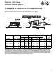
STERLING “RSD” SERIES INFRARED RADIANT HEATER 2) MINIMUM CLEARANCES TO COMBUSTIBLES Minimum clearances shall be measured from the outer surfaces as shown below: MINIMUM CLEARANCES TO COMBUSTIBLES Mounted Horizontally Mounted at 35° Angle Below Below Front Model RSD30 RSD33 RSD60 RSD66 RSD100 RSD120 RSD132 RSD140 RSD35 RSD40 RSD70 RSD80 w/Standard Reflector w/Reflector Extension w/Standard Reflector w/Reflector Extension w/Standard Reflector w/Reflector Extension 36" 72" 100" 72" 100" 36" 50"
STERLING “RSD” SERIES INFRARED RADIANT HEATER 3) SPECIFICATIONS Model No.
STERLING “RSD” SERIES INFRARED RADIANT HEATER 5) OPTIONAL PARABOLIC REFLECTOR EXTENSION ASSEMBLY The heater is completely factory assembled and requires no field assembly. If the optional parabolic reflector extension is utilized, locate and identify the end panels and side panels as shown in the following diagram. Attach the side panels as shown. Attach the end panels so that the end flanges of the end panels overlap the side panels.
STERLING “RSD” SERIES INFRARED RADIANT HEATER 7) GAS PRESSURE TABLE GAS TYPE MANIFOLD PRESSURE Natural Propane 6" W.C. 10" W.C. HEATER MODEL RSD (30, 35, 40, 60, 70, 80, 100 120, 140 & 160) RSD (33, 66, 100 & 132) *Minimum permissible gas supply pressure for purpose of input adjustment. 8) ELECTRICAL CONNECTIONS TYPICAL HEATER WIRING DIAGRAM FOR DIRECT SPARK IGNITION SYSTEM 6 SUPPLY PRESSURE *Minimum Maximum 7" W.C. 11" W.C. 14" W.C. 14" W.C.
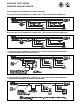
STERLING “RSD” SERIES INFRARED RADIANT HEATER FIELD CONNECTION AND THERMOSTAT WIRING DIAGRAMS A. LINE VOLTAGE (120V) THERMOSTAT CONNECTIONS – SINGLE HEATER PER THERMOSTAT B. LINE VOLTAGE (120V) THERMOSTAT CONNECTIONS – MULTIPLE HEATERS PER THERMOSTAT C. LOW VOLTAGE (24V) THERMOSTAT CONNECTIONS – MULTIPLE HEATERS PER THERMOSTAT – (POWER SUPPLIED FROM FAN CENTER RELAY) D.
STERLING “RSD” SERIES INFRARED RADIANT HEATER 9) VENTILATION Where unvented infrared heaters are used, natural or mechanical means shall be provided to supply and exhaust at least 4 cfm per 1000 Btu per hr input of installed heaters. Exhaust openings for removing flue products shall be above the level of the heaters. This heater requires ventilation in the building to dilute the products of combustion and provide fresh air for efficient combustion.
Warranty INFRARED HEATER Sterling (“the Manufacturer”) warrants to the original owner at the original installation site that the Sterling Model Infrared Heater will be free from defects in material and workmanship for one (1) year from the date of shipment from the factory.