
RSD Series Submittal


8
10
)
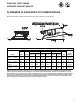
SEQUENCE OF OPERATION
The chart below shows the sequence of operation
for the normal operating cycle of the heater when
connected to a permanent 120V power supply and
the heater is turned on and off by a remote 120V
thermostat. (See Section 10)
If the fl ame is not sensed during sequence T2 then the
burner will automatically begin re-ignition sequence
T1. The ignition sequence will be repeated three times
with a 15 second inter-purge. If the fl ame is not
reestablished the heater will go to lockout.
9
)
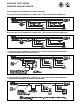
VENTILATION
Where unvented infrared heaters are used, natural
or mechanical means shall be provided to supply
and exhaust at least 4 cfm per 1000 Btu per hr input
of installed heaters.
Exhaust openings for removing fl ue products shall be
above the level of the heaters.
This heater requires ventilation in the building to
dilute the products of combustion and provide fresh
air for effi cient combustion. Power ventilation is
recommended and the minimum vent fl ow required
is as follows:
RSD30, RSD33, RSD35 140 cfm
RSD40 160 cfm
RSD60, RSD66, RSD70 280 cfm
RSD80 320 cfm
RSD100 400 cfm
RSD120 480 cfm
RSD132, RSD140 560 cfm
RSD160 640 cfm
If gravity ventilation is used, the required square feet of
inlet and outlet vent area (depending on height and
temperature difference) is as follows:
RSD30, RSD33, RSD35 0.49 s/f
RSD40 0.57 s/f
RSD60, RSD66, RSD70 0.98 s/f
RSD80 0.98 s/f
RSD100 1.48 s/f
RSD120 1.72 s/f
RSD132, RSD140 1.97 s/f
RSD160 2.30 s/f
The General Ventilation Rules outlined in ASHRAE
GUIDE AND DATA BOOK should be observed when
locating vents. Exhaust vents must be located at the
highest point above and in the vicinity of the heaters
and the inlet vents must be located below the level of
the heaters. Local codes may require that mechanical
exhaust systems be interlocked with the function
simultaneously or allow control of exhausters to
humidistat.
STERLING “RSD” SERIES
INFRARED RADIANT HEATER