STERLING “RSG” SERIES INFRARED RADIANT TUBE HEATER RSGS-2 RSG SERIES TUBE HEATERS RSG 25 (Check One) RSG 35 NATURAL GAS (Check One) RSG 45 PROPANE GAS EQUIPMENT USED: ACCESSORIES: Chain Mounting Kit: Vent Cap: Thermostat: Combustion Air Cap: Gas Pressure Regulator: Other: Gas Shut-Off Valve: Other: PROJECT: 3/17 260 North Elm St., Westfield, MA 01085 (413) 564-5540 Fax: (413) 562-5311 www.sterlinghvac.
STERLING “RSG” SERIES INFRARED RADIANT TUBE HEATER 1) GENERAL INFORMATION This heater complies with ANZI Z83.20 (current standard) and CSA 2-34. This heater is a self-contained infrared radiant tube heater for use in locations where flammable gases or vapors are not generally present (as defined by OSHA acceptable limits) and is intended for space heating of garages, vestibules and entry ways, workshops, enclosed patios, golf practice ranges and most industrial and commercial applications.
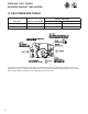
STERLING “RSG” SERIES INFRARED RADIANT TUBE HEATER 2) MINIMUM CLEARANCES TO COMBUSTIBLES Minimum clearances to combustibles shall be measured from the outer surfaces as shown in the following diagram. For reduced clearances below the heater, use the Deflector Kit (Part No. 43504010), described in Section 5, and maintain the minimum clearances specified in the notes below. Follow the instructions packaged with the kit for installation. Model No.
STERLING “RSG” SERIES INFRARED RADIANT TUBE HEATER 3) SPECIFICATIONS Model No. RSG 25 RSG 35 RSG 45 Btu/hr Input 25,000 35,000 45,000 Heat Exchanger Length Total Heater Length 16' 9'-3" Orifice Size Flue Restrictor Plate I.D. 7/8" 1" 1-1/8" Part Number #42741120 #42741041 #42741031 Natural Gas #42 #35 1/8" (0.094) (0.110) (0.125) Propane Gas 1.45mm 1.75mm 5/64” (0.057) (0.069) (0.078) Minimum Mounting Height* @ @ 45° Horizontal Angle 8' 8' 8' 8' 8' 8' * MOUNT HEATERS AS HIGH AS POSSIBLE.
STERLING “RSG” SERIES INFRARED RADIANT TUBE HEATER 4) DIMENSIONS 5
STERLING “RSG” SERIES INFRARED RADIANT TUBE HEATER 5) ACCESSORY PACKAGES A. Exhaust Hood Package, Part #42924000 Contains: Exhaust Hood Assembly, #42925540…...................… QTY–1 #8-18 x 1/2 Self-Drilling Screws, #02189030…........… QTY–2 B. Deflector Kit, Part #43504010 The Deflector Kit is available for use to reduce the clearances to combustibles below the heater. Refer to the “Minimum Clearances to Combustibles Table” in Section 2 when using this Deflector Kit.
STERLING “RSG” SERIES INFRARED RADIANT TUBE HEATER 6) GAS CONNECTIONS AND REGULATIONS US ONLY: A gas connector certified for use on a tubular type infrared heater per the standard for Connectors for Gas Appliances, ANSI Z21.24/CSA 6.10 is supplied for installation in US only. The gas connector is 36" long and 1/2" nominal ID, and must be installed as shown above, in one plane, and without sharp bends, kinks or twists.
STERLING “RSG” SERIES INFRARED RADIANT TUBE HEATER 7) GAS PRESSURE TABLE SUPPLY PRESSURE GAS TYPE MANIFOLD PRESSURE Minimum* Maximum Natural Gas 3.5" W.C. 5" W.C. 14" W.C. Propane Gas 10.0" W.C. 11" W.C. 14" W.C. *Minimum permissible gas supply pressure for purpose of input adjustment. This appliance is equipped with a step-opening, combination gas valve. The maximum supply pressure to the appliance is 14" W.C. or 1/2 P.S.I.
STERLING “RSG” SERIES INFRARED RADIANT TUBE HEATER 8) ELECTRICAL CONNECTIONS INTERNAL CONNECTION WIRING DIAGRAM — Direct Spark Ignition 9
STERLING “RSG” SERIES INFRARED RADIANT TUBE HEATER 9) THERMOSTAT CONNECTION WIRING DIAGRAMS A. LINE VOLTAGE (120V) THERMOSTAT CONNECTIONS – SINGLE HEATER PER THERMOSTAT B.
STERLING “RSG” SERIES INFRARED RADIANT TUBE HEATER C. LOW VOLTAGE (24V) THERMOSTAT CONNECTIONS – SINGLE HEATER PER THERMOSTAT Order 24V Relay Kit (Part No. 43274020) for Low Voltage (24V) thermostat connection. NOTES: a. If any of the original wire as supplied with the appliance must be replaced, it must be replaced with wiring material having a temperature rating of at least 105°C. (18 Ga. CSA 600V Type TEW) b.
STERLING “RSG” SERIES INFRARED RADIANT TUBE HEATER 10) VENTING A. BASIC FLUE VENTING — Venting must comply with the latest edition of the National Fuel Gas Code (ANSI Z223.1-latest edition) or the authority having jurisdiction. Other venting references are in the equipment volume of the ASHRAE Handbook. Maximum Vent Length ft.
STERLING “RSG” SERIES INFRARED RADIANT TUBE HEATER 7. When the vent pipe passes through areas where the ambient temperature is likely to induce condensation of the flue gases, the vent pipe should be insulated and a condensation drain should be provided. 8. Minimum clearance for single-wall flue pipe to combustible material shall be 6 inches. This may be reduced when the combustible material is protected as specified in the National Fuel Gas Code or the authority having jurisdiction.
STERLING “RSG” SERIES INFRARED RADIANT TUBE HEATER SINGLE HEATER VENTING (HORIZONTAL THROUGH SIDEWALL) This heater, when horizontally vented, must be installed with the approved venting system. When venting the heater horizontally through a combustible outside sidewall, the same requirements listed previously for venting Vertical Through The Roof apply except as follows: 1. For horizontal venting, the vent lengths may be as follows: • Minimum Equivalent Length = 5 ft.
STERLING “RSG” SERIES INFRARED RADIANT TUBE HEATER MULTIPLE HEATER VENTING (CONNECTIONS INTO A COMMON VENT OR MANIFOLD) Requirements for venting of multiple heaters are the same as described for “SINGLE HEATER VENTING” except as follows: 1. The common vent size and total vent height is normally determined by the number of heaters per common vent, length of horizontal connector runs, and connector rise. Connector lengths should be as short as possible and have a minimum 1/4 inch per foot rise.
STERLING “RSG” SERIES INFRARED RADIANT TUBE HEATER Multiple Heater Venting (Connections into a Manifold) VENT SIZING TABLE — Multiple Heater Venting Number of Heaters 1 2 3 4 RSG 25 4" 4" 4" 5" RSG 35 4" 4" 5" 5" RSG 45 4" 4" 5" 5" 5 5" 6" 6" Common Vent Diameter (If a size is not available use the next larger size.) The above illustrations and Table of Vent Sizes for Common Venting of Multiple Heaters are in accordance with the National Fuel Gas Code ANSI Z223.
STERLING “RSG” SERIES INFRARED RADIANT TUBE HEATER 11) AIR FOR COMBUSTION If indoor combustion air is to be supplied for a tightly enclosed area, one square inch of free area opening shall be provided below the heater for each 1,000 Btu/hr per hour of heater input. When outside air is used, the opening below the heater shall be one square inch of free area for each 4,000 Btu/hr of heater input. In contaminated atmospheres or high humidity areas, optional outside air for combustion is recommended.
STERLING “RSG” SERIES INFRARED RADIANT TUBE HEATER 18
STERLING “RSG” SERIES INFRARED RADIANT TUBE HEATER 13) SEQUENCE OF OPERATION The chart below shows the sequence of operation for the normal operating cycle. If the flame is not sensed during sequence T3 then the burner will automatically begin ignition sequence T2. If the flame is not re-established the heater will go to lockout.
Warranty INFRARED HEATER Sterling (“the Manufacturer”) warrants to the original owner at the original installation site that the Sterling Model Infrared Heater will be free from defects in material and workmanship for one (1) year from the date of shipment from the factory.