Operation and Installation Manual SCW Series Central Chilling Stations Important! Read Carefully Before Attempting to Install or Operate Equipment Part No. A0551795 Bulletin No. SC3-635.
Write down your unit serial number(s) ________________ ________________ here for future reference ________________ ________________ ________________ ________________ ________________ ________________ Sterling is committed to a continuing program of product improvement. Specifications, appearance, and dimensions described in this manual are subject to change without notice. © Copyright Sterling 2008 All rights reserved. Part No. A0551795 Page 2 of 77 Effective 4/11/2008 Bulletin No. SC3-635.
Safety Considerations Sterling SCW Series central chilling stations are designed to provide safe and reliable operation when installed and operated within design specifications, following national and local safety codes. To avoid possible personnel injury or equipment damage when installing, operating, or maintaining this equipment, use good judgment and follow these safe practices: ; Only PROPERLY TRAINED personnel familiar with the information within this manual should work on this equipment.
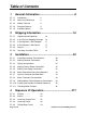
Table of Contents 1 General Information ................................................. 8 ; 1-1 Introduction ....... 8 ; 1-2 Necessary Documents 8 ; 1-3 Models Covered 9 ; 1-4 Standard Features 9 ; 1-5 Available Options 10 2 Shipping Information ............................................. 16 ; 2-1 Unpacking and Inspection 16 ; 2-2 In the Event of Shipping Damages 16 ; 2-3 If the Shipment is Not Complete 17 ; 2-4 If the Shipment is Not Correct 17 ; 2-5 Returns.............
; 4-6 Refrigeration Circuit 29 ; 4-7 Freezestat Control 29 ; 4-8 High Pressure Cutout 31 ; 4-9 Low Pressure Cutout 31 ; 4-10 Flow Switch ....... 31 ; 4-11 Control Nipple ... 32 ; 4-12 32 Control Probe .... ; 4-13 Chilled Water Manifold ; 4-14 5 32 Optional Condenser Water Manifold 32 Startup Checklists .................................................. 34 ; 5-1 Introduction .......
8-5 Viewing and Operating Chiller Pumps ................. 55 ; 8-6 Viewing Active Alarms and Handling Alarm Conditions 59 ; 8-7 Viewing and Setting System Temperatures 61 9 Routine Maintenance ............................................. 64 ; 9-1 Lubrication......... 64 ; 9-2 Condenser Maintenance 64 ; 9-3 Evaporator Maintenance 65 ; 9-4 Pump Motor Seal 65 9-5 Makeup Valve ..........................................................
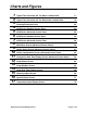
Charts and Figures 1 2 3 4 5 6 7 8 9 10 11 12 13 14 15 16 17 Typical Two-Circuit 60-195 Ton Water Cooled Chiller 11 Typical Two-Circuit 60-195 Ton Remote Air Cooled Chiller 13 Freezing Protection Curve 29 SCW Series Standard Control Panel 39 SCW Series Advanced Control Panel 40 SCW Series Standard Control Panel 44 SCW Series Advanced Control Panel 58 Main Menu Screen (Advanced Control Panel) 59 Chiller Status Screen (Advanced Control Panel) 61 Chiller Configuration Screen (Advanced Contro
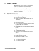
1 1-1 General Information Introduction Sterling SCW Series central water chilling stations are available in water-cooled and remote air-cooled designs. They differ only in the condensing media used. The SCW Series units are configured with two independent circuits using multiple compressors for each circuit. This manual lists information for these units. SCW Series chilling stations may be configured with stainless steel pump tanks for use as reservoirs for chilled water processes.
1-3 Models Covered This manual provides operation, installation, and maintenance instructions for the SCW Series central chilling stations. Model numbers are listed on the serial tag. A model number followed by Q indicates a specially constructed unit, and not all information in this manual may apply. Make sure that you know the model number, serial number, and operating voltage of your chiller if you contact Sterling.
1-5 Available Options SCW Series central chillers are available with options to tailor the unit to your requirements. Some are factory installed; some can be retro-fitted in the field. Consult Sterling sales for more information.
Model Number Nomeclature SCW W 060 SCW – Screw Compressor Central Chiller Condenser Type R – Remote Air Cooled W – Water Cooled (Nominal Unit Size) 060 075 090 100 115 145 165 195 SCW Series Central Chilling Stations Page 11 of 77
Figure 1 Typical Two-Circuit 60-195 Ton Water Cooled Chiller Model Cooling Capacity (tons) @ 50°F LWTc Capacity stages EER (BTUH/W) Evaporatord Nominal water flow (gpm) Condenserse Condenser connection (no manifold) Flange Conn. (in.) Evaporator manifold connection Victaulic Amp draw, nameplate Water-cooled (460/3/60 V)f Height Dimensions (in.) Width Depth Shipping weight (lbs) Max operating weight (lbs.) c d e f SCWW-xxx 75 90 74.9 88.8 Infinite Unloading 15.1 15.7 180 213 225 266 60 60.4 15.
Model Cooling Capacity (tons) @ 50°F LWTc Capacity stages EER (BTUH/W) Evaporatord Nominal water flow (gpm) Condenserse Condenser connection (no manifold) Flange Conn. (in.) Evaporator manifold connection Victaulic Amp draw, nameplate Water-cooled (460/3/60 V)f Height Dimensions (in.) Width Depth Shipping weight (lbs) Max operating weight (lbs.) c d e f 115 116.3 15.5 279 349 3 4 216 77 124 72 5,298 5,584 SCWW-xxx 145 165 146.0 166.3 Infinite Unloading 16.2 15.9 350 399 438 499 4 6 195 193.1 16.
Figure 2 Typical Two-Circuit 60-195 Ton Remote Air Cooled Chiller Model Cooling Capacity (tons) @ 50°F LWT Capacity stages EER (BTUH/W) Nominal water flow (gpm) Evaporator Evaporator manifold connection Victaulic No. of condenser fans per condenser Amp draw, nameplate Chiller (460/3/60 V) Condensers (per condenser) Dimensions (in.) of chiller Height Width Depth Dimensions (in.) of each Height condenser Width Depth Shipping weight (lbs) Chiller Condensers (each condenser) Max operating weight Chiller (lbs.
SCWR Series Remote Condenser Models Model Number SCWR60 SCWR75 SCWR90 SCWR100 SCWR115 SCWR145 SCWR165 SCWR195 Dia. in. 30 30 30 30 30 30 30 30 Motor hp c 1 ½ hp 3 ø 1 ½ hp 3 ø 1 ½ hp 3 ø 1 ½ hp 3 ø 1 ½ hp 3 ø 1 ½ hp 3 ø 1 ½ hp 3 ø 1 ½ hp 3 ø Fan(s) Refrigeration d Each Connections Charge Amps Air flow Discharge Liquid R-134a 460V Fans cfm e ODS(in.) ODS(in.) lbs. e 11.0 3 34,800 21/8 21/8 19 11.0 3 32,900 21/8 21/8 19 14.0 4 46,400 21/8 21/8 22 14.0 4 42,400 21/8 21/8 27 14.0 4 41,500 21/8 21/8 27 18.
2 2-1 Shipping Information Unpacking and Inspection You should inspect your equipment for possible shipping damage. Thoroughly check the equipment for any damage that might have occurred in transit, such as broken or loose wiring and components, loose hardware and mounting screws, etc. 2-2 In the Event of Shipping Damages According to the contract terms and conditions of the Carrier, the responsibility of the Shipper ends at the time and place of shipment.
2-3 If the Shipment is Not Complete Check the packing list as back-ordered items are noted on the packing list. In addition to the equipment itself, you should have: ; ................. Bill of lading ; ................. Packing list ; ................. Operating and Installation packet ; ................. Electrical schematic and panel layout drawings ; .................
2-6 Uncrating Your New Chiller ! WARNING ! DUE TO THE SIZE AND WEIGHT OF SCW SERIES CHILLERS, STERLING RECOMMENDS USING BONDED PROFESSIONAL MILLWRIGHTS TO UNLOAD AND MOVE SCW SERIES CHILLERS. Rig the chiller from the frame only, using spreader bars to prevent load transfer to any chiller components. Rig the frame from at least four points and balance the load before lifting to clear the skid. Use a forklift of adequate size when lifting the chiller by the fork pockets.
- Notes - SCW Series Central Chilling Stations Page 19 of 77
3 3-1 Installation Installation Location Considerations As with all equipment installations, follow all applicable codes and regulations. ; Locate close to the process to reduce piping expense. ; Locate adjacent to drain and city water sources. ; Consult a structural engineer to assure that the floor, mounting pad or structural steel support is of adequate strength. ; Allow for required service clearances necessary for condenser maintenance and easy access to all components.
! DANGER Improper electrical connections will damage the unit and cause serious operator injury or death! Compressor damage will occur if compressors are run backwards. Bring properly sized power leads and ground from a fused disconnect (installed by your electrician) to the unit. Provide external overcurrent protection to the unit, using circuit breakers or fuses. If you use fuses, make sure that they are dual-element timedelay fuses, sized according to your electrical code.
Note: • Never switch contactor leads or motor leads for reversing rotation. • Do not use contactor or motor leads for phase matching. • Compressor damage will occur if the compressor is run in reverse. The compressor motor protector checks for correct phasing and will not allow it to start in reverse. • If you discover that compressor rotation is reversed, correct it by switching any two main power leads into the disconnect switch or distribution block on the unit.
From Process The chilled water return for water returning back to the chiller from the process to be cooled and recirculated. Adjust the butterfly valve for the pressure drop that corresponds to the model number of the chiller. Pressure drop is equal to supply pressure minus return pressure Model Number SCWW/R60 SCWW/R75 SCWW/R90 SCWW/R100 SCWWR115 SCWW/R145 SCWW/R165 SCWW/R195 3-5 Water Side Pressure Drop Condenser (each) Evaporator (each) Flow (gpm) PD (psi) Flow (gpm) PD (psi) 91 4.0 72 5.3 102 4.
3-6 Water Connection Sizing Considerations Important! • Run all external chilled water connections with adequate size to the process. • Provide the largest possible openings and passages for the flow of chilled water through platens, dies, molds, or other pieces of equipment. • Minimum external pressure drop is critical for proper operation.
Two connections are made to each SCW Series unit: Condenser Water In The city or tower water supply inlet is located at the side or rear of the chiller. • Water pressure ≥ 25 psi (≥ 172.4 kPa/≥ 1.72 bars) • Water temperature ≤ 85°F (≤ 29ºC) Condenser Water Out The return outlet, located at the chiller side or rear is connected to a cooling tower inlet, a sewer or other approved discharge receiver. • A water regulating valve is an optional feature in the condenser water out line.
• No steam, hot air or fume exhausts drawn into the condenser coils. • Service accessibility. SCW Series condensing pressure with 95ºF (35ºC) condenser air R-134a = 171 psi (1,179 kPa/11.79 bars) Note: Due to the variables involved in remote air-cooled condenser installations, no set or standard piping procedure exists. Each installation must be designed and installed by qualified persons. Follow the instructions supplied with the condenser.
Condenser Fan On SCW Series remote air-cooled units, air should be drawn through the condenser and discharge up from the condenser. Changing fan rotation direction • Disconnect and lock out power at the fused disconnect. • If all fans are going backwards, reverse any two main power leads. • If only some of the fans are going backwards, switch any two of their respective motor leads.
4 4-1 Sequence Of Operation Staging 1. The system uses a PID control algorithm to regulate the chilled water temperature. As the required control effort increases or decreases, the system compressors are infinitely unloaded or turned on/off to keep the temperature at the specified set-point. 2. Compressor anti-recycle time is two (2) minutes. 4-2 Alarms If a fault occurs, that compressor or circuit is deactivated.
4-5 Chilled Water Circuit If your central chilling station is equipped with the optional integral pump tank, make the process cooling water supply connection at the P1 manifold at the left side of the pump tank at the exposed connection. Bring the process cooling water return connection to the Hot well of the tank on the right side at the flanged connection. Warm coolant (water and ethylene glycol mixture) returns from the process to the tank, then gets pumped through the evaporator where it is cooled.
If you want lower chilled water temperatures, you’ll need to mix process water with industrial- (not automotive) grade ethylene or propylene glycol with rust inhibitor to provide protection down to 20°F (12ºC) below the operating temperature you want. Figure 3 below shows the proper mixtures needed to provide protection to 20°F (12ºC) below the operating temperature you want. You can then reset the freezestat cutout temperature to a temperature of 10°F (6ºC) below the operating temperature you selected.
4-8 High Pressure Cutout This electro-mechanical safety feature opens the control circuit if the system condensing pressure exceeds a safe level. High pressure cutout setting Model SCW Series water-cooled and remote air-cooled chilling stations psi kPa bars 290 psi 2,000 kPa 20 bars Important! The high pressure cutout is a manual reset control, so you should reset it once. If the problem persists, call a refrigeration service technician to analyze the problem and to reset the control.
4-11 Control Nozzle All SCW Series chilling station evaporators have two control nozzles. The flow switch, freezestat, and flush port are located in the control nozzle. Pressure gages are mounted in the control nozzles to aid in achieving proper flow through the evaporator and balancing flows. Pressure drop between evaporator entering water pressure and evaporator leaving water pressure can be converted to gallons per minute using the pressure drop charts below.
- Notes - SCW Series Central Chilling Stations Page 33 of 77
5 5-1 Startup Checklists Introduction Important! These lists assume the installation information in this manual has been read and followed. Have new chillers started up and checked by a qualified refrigeration service technician. Sterling offers factory startup for SCW Series chilling stations. Call the Sterling Service Department at 1 (800) 233-4819 for more details.
; Complete all piping leading to and from the pump tank. Observe all applicable codes. ; Complete all electrical wiring. Observe all applicable codes. ; Prepare all related equipment in the system for operation. ; Check for proper compressor rotation direction. To confirm proper rotation: 1. Connect a phase meter and phase incoming power ABC. 2. Connect a refrigerant gauge to the suction service valve. Fully front seat the service valve and open one full turn. 3.
2. Close the gauge cock leading to the pump suction and open the gauge cock leading to the pump discharge. 3. Close the discharge butterfly valve, crack it open, then start the pump and observe the gauge. • If the gauge indicates within 15 psi (103.4 kPa/1.03 bars) below the pump curve, pump rotation is correct. Pump rotation is clockwise opposite the shaft end. • If the gauge indicates 20 psi (137.9 kPa/1.38 bars) or more below the pump curve, the pump is running backwards.
7. Operate the chiller, looking for leaks and listening for unusual noises or vibrations that could indicate improper operation. 5-4 Remote Air-Cooled SCW Series Startup Checklist ; Check the shipping papers against the serial tag to be sure chiller size, type and voltage is correct for the process. ; Check the transformer primary voltage connections to be sure they are configured for the electrical power you are using.
2. Connect a refrigerant gauge to the suction service valve. Fully front seat the service valve and open one full turn. 3. Bump start the compressor by switching off then on quickly 0.5 to 1 second. If the rotation is correct, the suction pressure will drop immediately. A rise in pressure will indicate the wrong rotation. If this occurs, change over two electrical phases of the incoming power supply (do not change phase at the compressor starter).
; Check the water level in the pump tank to be sure the pump does not run dry while the system piping is being filled. ; Check your work and proceed to the Startup procedure in the following section. 5-5 Remote Air-Cooled SCW Series Startup 1. Start the chiller by pushing the Start button on the control panel of the unit. 2. The touchscreen will display the Main Menu screen. 3.
5-6 Determining Flow Rate To determine flow: 1. Close the gauge cock leading to the pump suction side and open the gauge cock leading to the pump discharge. 2. Start the pump and make note of the discharge pressure in psi (kPa/bars). 3. Check the pump curve for the appropriate horsepower pump at the discharge pressure psi. 4. Project this point down to find the flow in gpm (lpm). 5. Process pumps can be left wide open if running amps are below full load amps. 5-7 Shutdown 1.
6 6-1 Graphic Panel Devices Indicator Lights and Control Switches (MMI) System On The green System On indicator lights when the main power switch is on and the control circuit is energized. Start The Start push-button lets you energize the unit. Stop The Stop push-button lets you de-energize the unit. Touchscreen Interface The color touchscreen interface gives you control over the chilling station.
-Notes- Page 42 of 77 SCW Series Central Chilling Stations
Using the Standard Operator Interface 7 7-1 Operator Interface Introduction The Standard touchscreen interface lets you control your SCW Series central chilling station. You can do such things as: • Control compressors and optional pumps • View current statuses of operation, such as pressures, temperatures, and capacities • Handle alarm conditions The sections in this chapter list special instructions for the standard operator interface. Note: The screens shown in this chapter are sample screens.
Figure 6 SCW Series Standard Control Panel 7-2 Using the SCW Series Standard Operator Interface Page 44 of 77 SCW Series Central Chilling Stations
7-3 Getting Started on the SCW Series Standard Operator Interface 7-4 Viewing and Operating Chiller Compressors Viewing Compressor Status Operating the chiller compressors Setting Compressor Lead/Lag Times and Activating Compressor Lead/Lag Operation Viewing Compressor Run Times 7-5 Viewing and Operating Chiller Pumps Viewing Chiller Pump Status Operating Chiller Pumps Setting Pump Lead/Lag Times and Activating Pump Lead/Lag Operation Viewing Pump Run Times SCW Series Central Chilling Stations Pa
7-6 Viewing Active Alarms and Handling Alarm Conditions ! CAUTION Never attempt to service a unit until a qualified electrician has opened and locked out the main disconnect using OSHA 1910.147 standards. All electrical connections must be done by a qualified electrician. ! WARNING Disconnect all power to the unit, let the unit cool down, and turn off the water prior to any servicing.
Setting System Temperatures SCW Series Central Chilling Stations Page 47 of 77
Using the Advanced Touchscreen Interface 8 8-1 Touchscreen Interface Introduction (MMI) The Advanced touchscreen interfaces let you control your SCW Series central chilling station. You can do such things as: • Control compressors and optional pumps • View current statuses of operation, such as pressures, temperatures, and capacities • Handle alarm conditions The sections in this chapter list special instructions for operating either touchscreen interfaces.
Figure 7 SCW Series Advanced Control Panel 8-2 Using the SCW Series Advanced Touchscreen Interface SCW Series Central Chilling Stations Page 49 of 77
8-3 Getting Started on the SCW Series Advanced Touchscreen Interface Figure 8 Main Menu Screen The Main Menu screen lets you gain access to: • “Active Alarms” contains the current alarm(s) of the system • “Al;arm History” contains the last thirty (30) alarms that were activated.
Press the Up or Down buttons on the right side of the screen to highlight “System Information” Press ↵ The chiller status screen displays: Figure 9 Chiller Status Screen The Chiller Status screen shows the status for compressors within the system.
be shown on this screen. Compressors will display one of the following states: 1. OFFLINE – This indicates that the compressor has been turned off in the compressor enable/disable screen. The compressor will not be called to operate until it has been re-enabled. The color code for this indication is black. 2. READY – Indicates that the compressor is enabled and ready to run. However, the current loading does not require the compressor to be running. This compressor will be automatically started when needed.
Touch the screen corresponding with the compressor you want to bring On-Line or Off-Line. The background color of the square turns green for On-Line and black for Off-line. Setting Compressor Lead/Lag Times and Activating Compressor Lead/Lag Operation While in the Configuration Menu, the compressors can be setup in a lead/lag configuration using interval hours.
Viewing Compressor Run Times From the Main Menu, use the Up or Down buttons to highlight the “Compressor Hourmeters” menu. Scroll to select the compressors. Then press ↵ to display the hourmeters. Note: This is a complete list of all compressors that may be included in the system. Any compressor that is not included in the system will not accumulate time.
Two hourmeters are kept for each compressor in the system. The first is a lifetime meter. This measures the total time that the compressor has been operational in the lifetime of the chiller. The second is a resettable hourmeter. This hourmeter can be cleared to monitor run time on specific intervals.
Press the Up or Down buttons to highlight either “System Information”. Press ↵ The Pump Status Screen appears Figure 12 Pump Status Screen Only pumps that are included in the system will be shown on this screen. Pumps will display one of the following states: 1. OFFLINE – This indicates that the pump has been turned off in the pump enable/disable screen. The pump will not be called to operate until it has been re-enabled. The color code for this indication is black. 2.
3. RUNNING – Pump is currently running. The color code for this indication is green. 4. FAULT – A safety on the pump indicates a fault condition and the pump has been deactivated. Once the problem is remedied, the pump will return to a READY state unless it is put in the OFFLINE state. The color code for this indication is red. Operating Chiller Pumps To turn on and off the pumps, start from the Main Menu, then: Press the Up or Down buttons to highlight either “Chilled Water Pump Tank Configuration”.
toggle the state of the pump from the ON-LINE to OFF-LINE state. Setting Pump Lead/Lag Times and Activating Pump Lead/Lag Operation While in the Configuration Menu, the pump lead/lag (rotation) can be enabled or disabled. Simply press the Process or Recirculation Pump Interval button on the screen to toggle between Enabled and Disabled. The interval between rotating pumps may also be setup in this screen. Press the CW Pump Rotation Interval button to bring up the time entry screen.
Pumps: Pump 1 Pump 1 Pump 2 Pump 2 Two hourmeters are kept for each pump in the system. The first is a lifetime meter. This measures the total time that the pump has been operational in the lifetime of the chiller. The second is a resettable hourmeter. This hourmeter can be cleared to monitor run time on specific intervals.
Chilled Water Circuit High Pressure (One per chilled water circuit) Chilled Water Circuit Low Pressure (One per chilled water circuit) Pump motor overload (One per system pump) If an alarm condition occurs, the follow screen is displayed: Figure 15 Alarm Condition Screen To acknowledge the alarm, press the alarm silence button to clear it. It will then appear in the alarm history screen.
Once a device has gone offline you will need to contact a licensed professional (electrician or refrigeration sevice company) to bring the device back online. ! CAUTION Never attempt to service a unit until a qualified electrician has opened and locked out the main disconnect using OSHA 1910.147 standards. All electrical connections must be done by a qualified electrician. ! WARNING Disconnect all power to the unit, let the unit cool down, and turn off the water prior to any servicing.
Use the Up or Down arrows to highlight “System Information” Press ↵ The system status displays: Figure 16 System Status Screen Note: If you have a metric version of the SCW Series controller, the screens display in converted metric values. Setting System Temperatures The chiller setpoints are set through the compressor configuration menu.
Press the Up or Down buttons to highlight “Chiller Configuration” Press ↵ Touch the “Process Set-point” button The input display screen appears: Figure 17 Temperature Input Display Screen SCW Series Central Chilling Stations Page 63 of 77
9 9-1 Routine Maintenance Lubrication Grease all fan bearings, fan motors, and pump motors that do not have permanently sealed bearings. Remove the grease relief plug (motors only) before adding grease. Failure to do so may dislodge the bearing grease retainer which will eventually cause bearing failure. Lubricate components regularly, based only on the component manufacturer’s specifications for frequency and lubricant.
9-3 Evaporator Maintenance The evaporator(s) may be accessed for back-flushing by removal of the 2” plug (approx. 51 mm) in the return control nipple and the flow switch in the supply control nipple. If the suggested piping recommendations have been followed, one circuit of a multiple circuit chiller may be back-flushed without shutting down the entire system. Check Y-strainer for any clogging. 9-4 Pump Motor Seal Pump seals require water for lubrication, so the pump(s) must never be run dry.
9-7 Preventive Maintenance Service A systematic preventive maintenance program helps avoid costly down time. Call the Service Department at Sterling to arrange a schedule of inspections. This service, described in Sterling Bulletin No. 10-106.3, is tailored to fit your maintenance requirements. Inspections include: ; Check refrigerant suction and discharge pressures. ; Check safety and operating controls. ; Check voltage and amperage of all motors. ; Check all electrical connections.
- Notes - SCW Series Central Chilling Stations Page 67 of 77
10 Troubleshooting Problem Possible Cause No power. Wrong voltage supplied to unit. Defective On/Off switch. Control circuit fuse blown. Unit does not run. Defective control transformer. Flow switch circuit is open. Pump motor off on overload. Unit is off on flow switch or pressure switch. Freeze control set higher than temperature of liquid in system. Pump runs, compressor does not. High pressure refrigerant cutout switch contacts open.
Problem Possible Cause Compressor internal overload open. Pump runs, compressor does not (cont’d). Compressor contactor holding coil open. Defective fan motor. Fan motor out on overload. Defective freezestat. Refrigerant low. Defective fan cycling control. Low refrigerant pressure switch contact open. Defective pump motor interlock to compressor control circuit. Broken wire in the compressor control circuit. Freezestat control setting is too high. Pump runs, compressor cycles at short intervals.
Problem Possible Cause Pump is running in reverse. Pump pressure is too low. Check for foreign matter. Process water pressure low, pressure at pump high. Evaporator frozen. Restricted condenser air flow. Refrigerant not feeding. Unit runs continuously, but not enough cooling power. Improper water/glycol solution. Poor heat transfer in evaporator. Unit low on refrigerant. Low water flow through evaporator. Inefficient compressor. Unit under-sized for application.
Service Notes SCW Series Central Chilling Stations Page 71 of 77
I Alarms Advanced Controls, 59 Standard Controls, 46 Available options, 10 Index Water Treatment Considerations, 24 Water-Cooled Condenser Connections, 24 Location considerations, 20 Checking Motor Direction, 26 Chiller Pumps Advanced Controls, 55 Chiller Shutdown, 40 Circuit Alarm Sequence, 28 Compressor Lead-Lag, 28 Compressor Staging Sequence, 28, 32 Condenser Maintenance, 64 Copyright information, 2 Determining Flow Rate, 40 Disclaimer information, 2 Electrical connections, 20 Electrical wiring schema
Alarms, 46 Getting Started, 45 Introduction, 43 Operating Chiller Compressors, 45 Water Connection Sizing Consideration, 24 Water Cooled Startup, 36 SCW Series Central Chilling Stations Water Cooled Startup Checklist, 34 Water Treatment Considerations, 24 Water-Cooled Condenser Connections, 24 Page 73 of 77
Service Notes Page 74 of 77 SCW Series Central Chilling Stations
Service Notes SCW Series Central Chilling Stations Page 75 of 77
Service Notes Page 76 of 77 SCW Series Central Chilling Stations
Technical Assistance Parts Department Call toll-free 7am–5pm CST or call [800] 423-3183, [262] 641-8610, or fax to [262] 641-8653 The ACS Customer Service Group will provide your company with genuine OEM quality parts manufactured to engineering design specifications, which will maximize your equipment’s performance and efficiency. To assist in expediting your phone or fax order, please have the model and serial number of your unit when you contact us.