
Product Manual

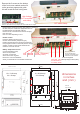


Remove the 2 screws on the bottom
of the front cover marked number 24
on the previous pages quick guide
this will reveal the main wiring area.
High Voltage
A/C cover plate
and clamp
D/C cable clamp
Remove the 2 screws on the A/C area and the 3 screws on
the D/C clamps to enable the appropriate wires to
be attached A/C input 90-160 volts A/C.
Ensure secure connections and correct crimping
tools are used
D/C 12 or 24V depending on unit.
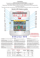
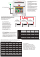
Remote control
Insert the Sterling remote control
into the remote socket ( telephone type )
Please note that when the remote is inserted the
front program controls on the local panel no longer
operate, control is in the remote. Remove the
remote to use local controls.
Battery Temperature sensor
Connect the battery temp
sensor to the position
as shown, connect the
sensor end to the neg stud
terminal on one of the batteries
which you think will be in the hottest environment.
Remote control
Live Neutral Earth ( European )
Live Neutral Ground ( USA )
1 2 3
red red red
Pos terminals on
3 x battery banks
Common Negative
Black (Europe) Yellow (USA)
3
5
8
[93]
5
1
8
[130]3
5
8
[93]
7
3
4
[198]
8
1
2
[215]
12
3
8
[315]
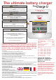
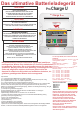
ProMariner
Pro Nautic iQ
12-60
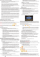
198 mm 7 3/4 inch
85 mm
3 3/8 inch
90 mm
3 ½ inch
260 mm
10 1/4 inch
85 mm
3 and 3/8 inch
215 mm
8 ½ inch
90 mm
3 ½ inch
44 mm
1 3/4 inch
dimensions
in inches
and ( mm )
12 v 10-40 amp
24 v 20 amp
12 v 50-60 amp
24 v 30 amp
Battery temperature sensor connection
A
FUSES
D/C
Cut out
90 x 62 mm
PCU 12V / 30-60A &
24V 20-30A have bolt
terminals as depicted above
rather than screw terminals.
PCU 12V 10A & 20A models have ring
terminal screw connectors as depicted above.
N.B. the 10A model has only 2 outputs, all other models have 3 outputs.