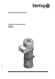
Operating Instructions Single Conveyor Unit SSE-2 SM4-615 P/N 882.00608.
SSE-2 Sterling Material Processing 5200 West Clinton Ave. Milwaukee, WI 53223 Telephone: (414) 354-0970 Fax: (414) 354-6421 www.sterlco.
SSE-2 Sterling Material Processing retains all rights to change the information in these operating instructions at any time without notice. SM4-615 We assume no liability for any errors or direct or indirect damage resulting in context with these operating instructions. Copying, translation or publication in any form except for personal use of purchaser requires approval from Sterling Material Processing. All rights reserved.
Please note that our address and phone information has changed. Please reference this page for updated contact information. These manuals are obsolete and are provided only for their technical information, data and capacities. Portions of these manuals detailing procedures or precautions in the operation, inspection, maintenance and repair of the products may be inadequate, inaccurate, and/or incomplete and shouldn’t be relied upon.
SSE-2 Table of contents 1. General instructions . . . . . . . . . . . . . . . . . . . . . . . . . . . . . . . . . . . . . . . . . . . . . . . . . . . . . . . 1-1 1.1. 1.2. 1.3. 1.4. 1.5. Warnings and symbols . . . . . . . . . . . . . . . . . . . . . . . . . . . . . . . . . . . . . . . . . . . . . 1-2 Explanations and information . . . . . . . . . . . . . . . . . . . . . . . . . . . . . . . . . . . . . . . 1-3 Legal basis . . . . . . . . . . . . . . . . . . . . . . . . . . . . . . . . . . . . . . . . . . .
SSE-2 8. Assembly instructions . . . . . . . . . . . . . . . . . . . . . . . . . . . . . . . . . . . . . . . . . . . . . . . . . . . . . 8-1 8.1. 8.2. 8.3. 8.4. 8.5. 8.6. 8.7. 8.8. 8.9. Assembly. . . . . . . . . . . . . . . . . . . . . . . . . . . . . . . . . . . . . . . . . . . . . . . . . . . . . . . . 8-2 Mounting on the processing machine . . . . . . . . . . . . . . . . . . . . . . . . . . . . . . . . . 8-4 Mounting onto a machine hopper . . . . . . . . . . . . . . . . . . . . . . . . . . . . . . . .
SSE-2 1. General instructions These operating instructions are to be used by all persons assigned activities connected with the equipment. SM4-615 » These instructions apply to all persons within the range of action of the equipment.
SSE-2 1.1. Warnings and symbols The following warnings and symbols are used in these operating instructions: » This symbol indicates danger to life! Fatal or serious injury is possible if the corresponding instructions, regulations or warnings are not observed. This symbol indicates that serious injury is possible if the corresponding instructions, regulations or warnings are not observed.
SSE-2 1.2. Explanations and information Various terms and designations are used in these operating instructions to ensure clarity. Therefore please note that the terms used in the text stand for the corresponding explanations listed below. • Equipment ”Equipment” can mean an individual unit, a machine or an installation. • Operating personnel The ”operating personnel” are persons operating the equipment on their own responsibility or according to instructions.
SSE-2 2. Safety instructions » These safety instructions apply to all persons within the range of action of the equipment. Please inform all persons within the range of action of the equipment of the direct and indirect hazards connected with the equipment. These operating instructions are to be used by all persons assigned activities connected with the equipment. Knowledge of the English language is prerequisite.
SSE-2 2.1. For your safety General The operating personnel of this equipment must be at least 16 years old. Please read these operating instructions carefully before taking into operation for the first time. Contact us should questions arise. This avoids injury and damage to equipment! These operating instructions must be kept available at all times at the place of operation of the equipment.
SSE-2 Assembly Compare the connected loads with those of the mains supply. Danger of injury through electrical shock! When using lifting gear, please observe the pertaining regulations. Caution: Danger of accidents! Do not modify, add other equipment or change the design of the equipment without the approval of the manufacturer. Caution: Danger of accidents! Attachments not supplied by Sterling must be manufactured in accordance with safety regulation EN 294.
SSE-2 Operation Appoint an equipment foreman to be responsible for the equipment. Ensure that the operating personnel are provided detailed instruction in the operation of the equipment. Improper operation results in danger of accidents! When the main switch is switched off for reasons pertaining to safety, it must be secured against unauthorized activation. Caution: Danger of accidents! Repair work may be carried out by trained personnel only.
SSE-2 2.2. For the operating safety of the equipment Never change settings if the consequences are not precisely known. Use only original Sterling spare parts. Please observe the maintenance schedule. Keep record of all maintenance and repair work. Please note that electronic components may be damaged by static discharge. Check all electrical connections for proper fit before the equipment is taken into operation for the first time and at regular intervals.
SSE-2 3. Putting into operation » This chapter is intended for operating personnel. Prerequisite for this chapter is general knowledge of the operation of conveying systems. Also prerequisite for this chapter is that the functional description has been read and understood. Ensure in each case that the operating personnel are sufficiently informed. Make sure the adhesive tape has been removed from the exit flap. SM4-615 F Make sure the plastic stopper has been removed from the material inlet nozzle.
SSE-2 3.1. Checking the pipe system Remove the flexible hose from the connected material takeup. Close the open end of the hose with your hand. Connect the unit to mains supply by the device plug. If the turbine is operating, your hand must feel the suction within few seconds. If you don’t feel the vacuum it means that the pipe system is not tight. Check the pipe system and seal any untight points you may have identified. Reconnect the conveying hose.
SSE-2 3.2. Adjusting the suction pipes The suction pipes have to be adjusted exactly to ensure troublefree operation. 1. Set the suction pipes to their home position. & At home position the inner pipe of the suction pipe protrudes about 120-160 mm (4.75" - 6.25") from the outer pipe at the top end. 2. Start a conveying operation. Connect the unit to mains supply by the device plug. 3. Observe the flexible hose at the suction pipe. The flexible hose must not show any pulsating movement. 4.
SSE-2 3.3. Setting the controller F The filling capacity of the hopper loader may not exceed the material inlet. & The setting is independent of the conveying line and the material to be conveyed. It is only possible to set the conveying time/line clear time when the unit is not conveying any material. Setting the conveying time Press the “arrow key”. & The conveying time which was last selected appears in the display. 1-99 seconds may be set for the conveying time.
SSE-2 Setting the line clear time Press the “change-over” key and then the “arrow key”. & The line clear time which was last selected appears in the display. 0-99 seconds may be set for the line clear time. F If no line clear valve has been installed enter “0". 3.4. Initial conveying operations Metal shavings may be inside the pipe from cutting down pipes into lengths. These are pulled during the first conveying process and collected in the separator. F This material should not be used again. 3.5.
SSE-2 4. Error and error correction » This chapter is intended for the operating personnel of the equipment. Prerequisite for this chapter is general knowledge of the operation of conveying systems The “Start-up” description must have been read and understood. SM4-615 Ensure in each case that the operating personnel are sufficiently informed.
SSE-2 If a disturbance occurs in the unit, an alarm message will be issued (option, only if the alarm indicating device has been activated). & An “E” appears in the display and an error number. The alarm indicating device (signal siren, horn) reacts. F The control system can only restart operation when the malfunction has been corrected. Press the “acknowledgement key”. & The cause of the malfunction will not be corrected by pressing the “acknowledgement key”.
SSE-2 “E2" If the control system becomes too hot during operation (>70°C, 158°F) the “E2" alarm message is displayed and the unit is switched off. Ensure that the control system is sufficient cooled. The unit starts automatically after the cooling down phase.
SSE-2 5. Maintenance This chapter is intended for persons with skills in electrical and mechanical areas due to their training, experience and received instructions. Personnel using the instructions in this chapter must be instructed of the regulations for the prevention of accidents, the operating conditions and safety regulations and their implementation. Ensure in each case that the personnel are informed. For maintenance work taking place at heights of over approx.
SSE-2 F Please observe the maintenance intervals. Before starting maintenance work, clean the equipment of oil, fuel or lubricants. Ensure that materials and incidentals required for operation as well as spare parts are disposed of properly and in an environmentally sound manner. Use only original Sterling spare parts. SM4-615 Keep record of all maintenance and repair procedures.
SSE-2 5.1.
SSE-2 5.2.1. Changing the sealing ring of the outlet flap Open the toggle-type fasteners (A) and the flap (B) of the hopper loader. Draw the old sealing ring (C) off the nozzle of the material outlet. Install the new sealing ring (C). A B C Installation sealing ring F Observe the direction of installation (C). Close the flap (B) and the toggle-type fasteners (A). Install the hopper loader.
SSE-2 5.2.2. Adjusting the flap switch Remove the connecting plug “flap switch” from the connection housing of the hopper. Connect an ohmmeter to PINS 2 and 3 of the connecting plug “flap switch”. Release the nuts (A) of the flap switch (B) until the support can be displaced. Open the outlet flap (C) so far that the front tip of the outlet flap is approx. 30 mm (1.2") away from the sealing surface. 3O Displace the flap switch (B) until the contact of the magnet switch is closed.
SSE-2 5.2.3. Cleaning the unit Open the tension ring. Fold the turbine head upwards. Remove the sieve. Clean the sieve by means of compressed-air. Clean the hopper loader by means of a vacuum cleaner. Mount the sieve. Pay attention for proper fit. Mount the turbine head. Mount the tension ring. or optional, active cleaning Open the tension ring. Fold the turbine head upwards. Remove the filter. Clean the filter by means of compressed-air. Clean the hopper loader by means of a vacuum cleaner.
SSE-2 Open the toggle-type fasteners (A) and the flap (B) of the hopper loader. Check the filter cloth (C) and the wire cloth (D) for material residue. Clean the filter by means of compressed air. Close the flap (B) and the toggle-type fasteners (A) on the flap of the hopper loader. A B C D Install the unit.
SSE-2 5.3. Replacing carbon brushes at turbine » This work must be carried out by qualified personnel only. Disconnect the unit from mains supply by the device plug before you begin with works on the controller. Danger to life! Depressurize all system sections of the equipment (only units with active cleaning). Disassembly the unit. Remove the screws (A) at the lid. Remove the lid (B). Remove the latchet carefully from the brush holder (C). B A Remove the cover (D). Loosen the brush holder lock.
SSE-2 Observe that no cables will be squeezed. F Carbon brushes can be replaced twice. After that the turbine has to be completely replaced.
SSE-2 6. Functional description » This functional description is intended for all operating personnel of the equipment. Prerequisite for this functional description is general knowledge of conveying systems. SM4-615 Ensure in each case that the operating personnel are sufficiently informed.
SSE-2 6.1. General The single conveyor unit functions according to the principle of suction conveyance. A high-performance turbine, mounted permanently on the device, provides for the vacuum that is required to convey the material into the separator. In the separator the material is separated from air. After the conveying time is finished the turbine is switched off and the material emptied into the material intermediate hopper.
SSE-2 6.2. Controller The control system is mounted on the separator lid. The setting for the conveying time and the line clear time are made via the keys (A1: “change-over” key, A2: “arrow key”) on the front of the control system. The values which have been set will be displayed on the display (B). The values which have been set are maintained after the machine has been shut off. 3 LEDs indicate the respective modes of operation: cleaning (C), conveying (D), line clearing (E).
SSE-2 Optional: If a material clearing valve has been installed residues of flowing material will be cleaned from the conveying line during the line clear time. If a disturbance occurs in the unit, an alarm message will be issued (only if the alarm indicating device has been activated). & An “E” appears in the display and an error number. SM4-615 The alarm indicating device (signal siren, horn) reacts.
SSE-2 7. Transport, Assembly and Storage » This chapter is intended for all operating personnel of the equipment. Personnel using these instructions must be instructed in the regulations for the prevention of accidents, the operating conditions and safety regulations and their implementation. Ensure in each case that the operating personnel are sufficiently informed. Please inform all persons within the range of action of the equipment of the direct and indirect hazards connected with the equipment.
SSE-2 7.1. Transport and Packing » Please ensure adequate carrying capacity of the lifting equipment. The equipment pass a rigorous operating test in the factory and are packed carefully to avoid transport damage. Please check packing on delivery for transport damage. The inlet and discharge flanges are sealed with plugs, so that no dirt can enter during transport. Plugs must be removed before assembly. Packing materials should be disposed of according to environmental laws or reused.
SSE-2 8. Assembly instructions » These installation instructions are intended for persons with skills in electrical and mechanical areas due to their training, experience and received instructions. Personnel using these installation instructions must be instructed in the regulations for the prevention of accidents, the operating conditions and safety regulations and their implementation. Ensure in each case that the personnel are informed.
SSE-2 8.1. Assembly The single conveyor unit is insensitive to shocks and can be mounted directly onto the processing machine, on a machine hopper, a drying hopper or a dosing and blending unit. The equipment is delivered as a complete assembly. Unpack the equipment. Remove the plastic stopper (A) from the material inlet nozzle. Open the flap (B) and remove the adhesive tape from the exit flap. F The controller must be freely accessible.
SSE-2 Mounting on fixed machine throats or intermediate containers is done by means of strap retainers. Please check during assembly that the admissible bearing loads are not exceeded. Mount the conveyor in such a way that the outlet flap swings in a right angle to the direction of machine movement. Please check that all connecting points are tight to ensure that the conveying performance is not impaired.
SSE-2 8.2. Mounting on the processing machine A material hopper VT 1,0 is required: Mount the material hopper onto the flange of the processing machine. Mount the unit onto the material hopper. VT 1,0 F Observe the bearing capacity of the machine flange. 8.3. Mounting onto a machine hopper A welding flange EF 190 is required: L Please observe all safety regulations for the operation of welding equipments. Always wear a safety goggle. Weld the welding flange into the machine hopper lid.
SSE-2 8.4. Mounting onto mixing hoppers with lateral inlet A material hopper VT 1,0 is required: Mount the material hopper onto the swan-neck of the mixing hopper. Mount the unit onto the intermediate hopper. VT 1,0 F Observe the bearing capacity of the machine flange. 8.5. Mounting onto dosing station DT 30 A dosing hopper DT 30 (320 mm high) is required: Mount the dosing hopper directly onto the dosing container of the dosing station DT 30. Mount the unit onto the dosing hopper.
SSE-2 8.6. Material feed Suction pipes type MV may be tilted by approx. 45 degrees in either direction to the vertical. Additional fastening is not required. When conveying from the bottom of storage containers (silos), a suction box with 1-3 suction pipes is required. The connection of the suction pipes must be carried out with a piece of flexible line to provide sufficient movement. Please observe that the length of the hose should not exceed 3 meters (10 feet).
SSE-2 8.8. Pipework If PVC hoses are used for conveying, they must be grounded: draw out the copper lead on both ends of the hose and jam it between hose and tube. For fastening, use threaded clamps. 8.9. Electrical connection » The regulations of the local Electricity Board must be observed. Before connection to the electricity supply, it should be ensured that the supply voltage and the power frequency are in accordance with the data on the name plate of the machine.
SSE-2 8.9.1. Installation of the “flap switch” signal line Insert the appliance plug of the “flap switch” signal line into the “flap switch” connector (A) on the lower side of the controller. 8.9.2. Installation of the signal line of the SKW (optional) Insert the appliance plug of the "SKW (= Two Component Proportioning Valve)” signal line into the “SKW” connector (B) on the lower side of the controller.
SSE-2 8.9.3. Installation of the alarm indicating device (optional) » This work must be carried out by qualified personnel only. Disconnect the unit from mains supply by the device plug before you begin with works on the controller. Danger to life! The connection is potential-free and rated for no more than 100 VA. & An additional alarm indicating device (e.g. horn, signal light) can be connected. You need an “acknowledgement key” for 24 V (e.g. by Rafi Company).
SSE-2 8.10. Compressed-air supply (only SSE-2 with active cleaning) For operating the cleaning device, a compressed-air supply is necessary. Check compressed-air piping for correct installation and assembly. Check fittings, length and quality of the hose connections for agreement with requirements. The operating pressure is 5-6 bar (72-87 PSI) (system overpressure). Check the compressed-air supplied by the plant’s supply network. Adjust compressed-air pressure to 5-6 bar (72-87 PSI) (system overpressure).
SSE-2 9. Technical data These operating instructions are to be used by all persons assigned activities connected with the equipment. SM4-615 » These instructions apply to all persons within the range of action of the equipment.
SSE-2 SSE-2 Basic Version • Integrated control with: - LED-display - indication of the respective modes of operation - adjustable conveying time - adjustable line clearing time - two component valve output • Integrated vacuum pump • Integrated filter-sieve • Parts coming in contact with material are made of stainless steel • Simple mounting to dosing and blending units due to compact and weight saving design Optional Features • Integrated filter with automatic cleaning • Alarm indicating device - display
SSE-2 Dimension Sheet SM4-615 Dimensions and data without obligation. Dimensions in mm. Specifications may be subject to alterations.
SSE-2 10. Spare parts list » & This spare parts list is intended to be used only by trained personnel. Other persons are not permitted to modify or repair the equipment.
SSE-2 SM4-615 SSE-2, 230 V, 50 Hz / 110 V, 60 Hz Spare parts list 10-2
SSE-2 10.1. SSE-2, 230 V, 50 Hz Pos. Order no.
SSE-2 10.2. SSE-2, 110 V, 60 Hz Pos. Order no.
SSE-2 10.3. SSE-2, 230 V, 50 Hz with active cleaning Pos. Order no. Designation Wear Code 1 37755 Filter with sealing 2 37222 Basket 3 82593 Solenoid valve B 4 97745 Bush D 5 37800 Breather tube D A 10.4. SSE-2, 110 V, 60 Hz with active cleaning Pos. Order no.
SSE-2 10.5. Accessories SM4-615 F Please observe the operating manuals in chapter 11.
SSE-2 11.
SSE-2 12. Electrical manual » This electrical manual is intended to be used only by Sterling service personnel and trained personnel authorized by Sterling. Other persons are not permitted to modify or repair the equipment. o Connection diagram no.