Operation, Installation & Service Manual SSL and SSIL Series Sight Glass Hopper Loaders Important! Read Carefully Before Attempting to Install or Operate Equipment Part No. 882.00149.00 Revision C Bulletin No.
Write down your hopper ________________ ________________ loader serial numbers ________________ ________________ here for future reference ________________ ________________ ________________ ________________ Performance figures stated in this manual are based on a standard atmosphere of 59°F (15°C) at 29.92” Hg (1,014 millibars) at sea level, using 60 Hz power. Altitude is an important consideration when specifying hopper loaders.
Shipping Information Unpacking and Inspection You should inspect your SSL/CSL or SSIL/CSIL hopper loader for possible shipping damage. If the container and packing materials are in reusable condition, save them for reshipment if necessary. Thoroughly check the equipment for any damage that might have occurred in transit, such as broken or loose wiring and components, loose hardware and mounting screws, etc. In case of breakage, damage, shortage, or incorrect shipment, refer to the following sections.
If the Shipment is Not Complete Check the packing list. The apparent shortage may be intentional. Back-ordered items are noted on the packing list. You should have: ; SSL/CSL Series or SSIL/CSIL Series hopper loader(s) with controller(s) ; Bill of lading ; Packing list ; Operating and Installation packet ; Electrical schematic and panel layout drawings ; Component instruction manuals Re-inspect the container and packing material to see if you missed any smaller items during unpacking.
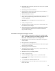
Table of Contents CHAPTER 1: SAFETY ................................................................ 7 CHAPTER 2: FUNCTIONAL DESCRIPTION.............................. 8 2-1 2-2 2-3 2-4 2-5 2-6 Introduction.................................................................................................................. 8 Necessary Documents ................................................................................................ 8 Equipment Function ...................................................
5-12 Shutting Down the Hopper Loader using the Series One Plus Controller................. 43 CHAPTER 6: SERIES ONE PLUS SPI COMMUNICATIONS .. 44 6-1 6-2 6-3 SPI Network Functions.............................................................................................. 44 Setting Up the SPI Function ...................................................................................... 44 Operating under SPI Control .....................................................................................
Chapter 1: Safety SSL/CSL Series hopper loaders and SSIL/CSIL Series sight glass hopper loaders are designed to provide safe and reliable operation when installed and operated within design specifications, following national and local safety codes. To avoid possible personnel injury or equipment damage when installing, operating, or maintaining this equipment, use good judgment and follow these safe practices: ; Follow all SAFETY CODES. ; Wear SAFETY GLASSES and WORK GLOVES.
Chapter 2: Functional Description 2-1 Introduction SS/CS Series hopper loaders economically and efficiently load free-flowing pellets or granular materials from supply containers into machine bins or other receivers. They are a modular, stainless steel component design using significant operational advantages. Their engineered construction permits easier cleaning and maintenance, and they can be quickly and easily reconfigured to accommodate future production requirements.
2-3 Equipment Function SS/CS Series hopper loaders are efficient conveyers of free-flowing pelletized or granular materials from supply containers into machine bins or other receivers. You can customize operation by adjusting operating parameters accessible through a menu system built into the control. Simple electrical and compressed air connections are all that’s needed for operation; a central vacuum system is not necessary.
• Removable inlets on 0.2, 0.4, 0.8, and 1.6 cu. ft. (5.6, 11.3, 22 and 45 liter) models only • Glazed polyester reinforced flat filter • Hopper-mounted junction box with 12 feet (3.
• Hopper-mounted junction box with 12 feet (3.6 m) of cable to a field-mounted 115/1/60 control box • Removable inlets on 0.2 and 0.4 cu. ft. (5.6 and 11.3 liter) models • Accumulator blowback is standard on 0.2 and 0.4 (5.6 and 11.
Remote Proportioning Valve The remote proportioning valve (SPV/CPV) option lets you economically and efficiently proportion two (2) different free-flowing granulated materials in a material conveying system. The most common application is mixing virgin and regrind materials in a plastic processing operation. SPV/CPV installation options include a wall-mount bracket and floor stand.
Figure 1: Typical SSL/CSL Series Hopper Loader • 10” Clearance Cutout with (6) ¼” bolt holes equally spaced on an 11” circle. SSL/CSL03 Hopper Loader A We are committed to a continuing program of product improvement. Specifications, appearances, and dimensions are subject to change without notice.
Figure 3: SSL/CSL Series Dimensions, Specifications, and Maximum Machine-Side Throughput American Standards Capacity cu. ft. 0.1 A 7.0 0.2 0.4 0.8 5.75 1.6 B 173/8” Dimensions in inches C D 3 12” 6 /8” 211/8” 271/8” 51/2” 111/2” 30 ¼” 36 ½” 12” E 3 1 /4” 4” F 3 6 /8” 91/8” 12” 4” 10 ½” 12” 4” 91/8” 141/8” 17 ¾” 12” 4” 14 1/8” C 16.2 14.0 29.2 27 45 D 30.5 30.5 30.5 12 12 E 4.4 10.1 10.1 10.1 10.1 F 16.2 23.2 23.2 36 36 Metric Standards Capacity liters 2.8 5.6 11.
Figure 4: Typical SSIL/CSIL Series Sight Glass Hopper Loader SSIL 06 Model SSIL/CSIL03 Sight Glass Hopper Loader C D A B SRIL01.DWG I J H G E E HOPSRIL.DWG We are committed to a continuing program of product improvement. Specifications, appearances, and dimensions are subject to change without notice.
Figure 5: SSIL/CSIL Series Dimensions, Specifications, and Maximum Machine-Side Throughput American Standards Capacity cu. ft. 0.1 0.2 0.4 A 275/8” 351/4” 411/4” B 17” 191/2” 253/4” C 63/8” 91/8” 91/8” Dimensions in inches D E -sq. G -sq. 13/4” 4” 2” 3” 7” 31/2” 3” 7” 31/2” H -sq. 11/4” 23/4” 23/4” I -sq. c 21/2” 51/2” 51/2” J 2” 3” 3” H -sq. 3.2 7.0 7.0 I -sq. c 6.3 14.0 14.0 J 5.1 7.6 7.6 Metric Standards Capacity Dimensions in cm liters A B C D E -sq. G -sq. 2.8 74.0 41.9 16.2 4.4 10.2 5.1 5.
Chapter 3: Installation 3-1 Work Rules Install, operate, and maintain this equipment according to all applicable work and safety codes. This includes, but is not limited to: OSHA, NEC, CSA, and any other local, national, and international regulations. Obey these specific work rules: ; Read and follow these instructions when installing, operating and maintaining this equipment. If the instructions become lost or unreadable, obtain a new copy from the manufacturer.
For new installations or mounting on other manufacturer’s equipment, a hole location template is included in the information packet. Important! We are not responsible for equipment damage from excessive processing machine vibrations. 3-5 3-6 Mounting Tips • Run a bead of silicone sealant around the mounting flange before seating the hopper loader. This provides an additional seal. • Use rivets to mount the hopper loader. Bolts, nuts, and washers can loosen, fall into, and damage process equipment.
Make sure that the material demand sensor is installed with the proper amount of clearance, and that it is free of obstructions. If the installation has the SSL/CSL or SSIL/CSIL Series hopper loader wired directly to a power main, you must install a fused disconnect with lockout to allow safe operation and maintenance. Make sure all connections are tight. 3-9 Installing the Remote Control Box Optional-Series One Plus Controller Only The remote option permits mounting a control up to 9 feet (2.
provides volume-fill control. When the hopper loader is full, the LED on the proximity switch should light and trigger the dump sequence. If the switch does not reliably sense the material you are conveying, adjust switch sensitivity. Turn the potentiometer (or pot) clockwise to increase sensitivity, counterclockwise to decrease sensitivity.
Chapter 4: Series One Controller Operation 4-1 Pre-Startup Checklist ; Are all electrical connections correct, secure, and to code? ; Is the compressed air connection secure and safe? ; Is the hopper level and mounted securely? ; Are the flex hose and pick-up wand secure? ; Can the material level switch activate without obstruction? ; Can the material discharge valve swing without obstruction? 4-2 Operating Sequence 1. Blowback sequence. 2. Motor starts. 3.
Figure 6: Series One Graphic Panel BVUP MPBEFS TM SERIES ONE ON OFF A0542127 22
4-3 4-4 Starting the Hopper Loader 1. Insert the pickup probe into the material supply. 2. Turn on compressed air to the unit. 3. Plug in power to the control enclosure. 4. Move the power switch on the Series One graphic panel to the ON position. Changing the Conveying Sequence ! DANGER DISCONNECT POWER BEFORE OPENING THE CONTROL BOX. Electric current, CAPABLE OF CAUSING INJURY OR DEATH, MAY BE PRESENT in the controller enclosure during these procedures.
To select a sequence (see Figures 7 and 8 on the following pages): 4-5 1. Turn off and disconnect power to the unit. 2. Remove the controller box cover. 3. Move the DIP switches on the DIP switch array labeled SW1 to one of the sixteen (16) available configurations as shown in Figure 8. 4. Replace the controller box cover. 5. Reconnect power to the Series 1 controller and prepare the unit for operation.
Figure 7: Conveying Dip Switch Chart, Program A0541578 SSL/CSL 03 and SSIL/CSIL03 Models 1.
Figure 8: Conveying Dip Switch Chart, Program A0536814 SSL/CSL 06, 11, 23 and 45 and SSIL/CSIL 06 and 11 Models 10 SECONDS 6 1 2 3 15 SECONDS 4 BLOWBACK PULSES 1 2 OFF OFF OFF OFF 1 1 2 6 3 PULSES OFF 1 2 OFF 2 3 PULSES OFF OFF OFF 4 1 ON OFF OFF 1 ON ON OFF 2 3 OPEN OFF 1 2 ON ON OFF 4 1 OFF OFF OFF 40 SECONDS 45 SECONDS 2 3 ON ON 4 1 2 3 ON ON ON OFF 2 OFF 3 4 OFF OPEN 70 SECONDS 4 1 2 ON ON ON 3 OFF 4 ON OFF OPEN 90 SECONDS
Chapter 5: Series One Plus Controller Operation The Series One Plus controller is an optional controller that includes the following features: 5-1 • Sensor-driven volume fill cycle to assure full load discharge for each cycle • Operator programming of blowback pulses to optimize efficiency • Accurate fill cycle counts up to 9,999 on the batch counter to assist in estimating material usage • No Fill alarm with automatic shutdown notifies the operator of an empty material source or lack of material f
Figure 9: Series One Plus Graphic Panel BVUP MPBEFS TM SERIES ONE PLUS 60 ADJUSTMENTS MADE WHILE RUNNING PROPORTIONING ADJUSTMENTS UNTIL S CLEAR ADJUST % OF MAT'L "B" S SAVE NEW SETTING BATCH COUNTER RESET SCROLL START/STOP VACUUM % OF MAT'L "B" DISPLAYED UNTIL 4-DIGIT BATCH CNTR IS DISPLAYED MATERIAL "A" RESETS BATCH COUNTER TO 0000 CLEAR ERROR BLOWBACK MATERIAL "B" CLEAR AN MENU ADJUSTMENTS AND INSTRUCTIONS: MENU TITLE (FACTORY SETTING) [ ] MAXIMUM LOAD TIME : 0-360 (60) SEC.
5-2 Operating Sequence 1. Blowback sequence. 2. Motor starts. 3. The flapper discharge valve seals under vacuum. 4. Material conveys. 5. Hopper loader hopper fills. 6. Vacuum timer times out. 7. Motor stops. 8. Blowback sequence begins, the flapper discharge valve opens under the weight, and material dumps. Steps 1 through 8 repeat automatically. If the level switch remains open, the hopper loader remains idle until the material level in the bin drops and frees the discharge valve.
SCROLL SCROLL Key Press the S START/STOP SCROLL SCROLL key to display: • available menus when the controller is in Standby mode. • operations screens such as batch counter and SPV settings when the controller is operating.
BLOWBACK BLOWBACK Indicator The BLOWBACK indicator lights when the air solenoid is open. MATERIAL "B" MATERIAL “B” Indicator The MATERIAL “B” indicator lights when the Material B port is open. 5-4 Starting Up the Hopper Loader for the First Time Using the Series One Plus Controller Non-Proportioning Models 1. Insert the pickup wand into the material supply. 2. Turn on the compressed air to the hopper loader. 3. Apply power to the controller.
Note: You can adjust the maximum vacuum time from 0 to 360 seconds. See Section 5-11, Menu 1. When the proximity sensor trips or sixty (60) seconds elapses, the vacuum motor shuts off for three (3) seconds to relieve vacuum in the hopper and to allow the material to dump. The BLOWBACK LED flashes and the screen displays ---- as a four (4) -pulse blowback cycle occurs. Note: You can adjust number of blowback pulses from 0 to 16 pulses. See Section 5-11, Menu 2.
Note: Press and hold the UP key and DOWN key together simultaneously while applying power to restore all factory defaults. CLEAR As the controller powers up, the screen displays in succession: • PLUS for three seconds • the software version number n.nn • the standby mode display. 4. SCROLL key repeatedly until the screen displays 3, Press the the percentage of Material B menu. 5. Press the menu. 6. Press the press the 7.
Note: You can adjust the maximum vacuum time from 0 to 360 seconds. See Section 5-11, Menu 1. The MATERIAL “A” and MATERIAL “B” LEDs alternate on and off as set in Steps 4 to 6 above. This indicates the proportioning valve cycle. Example: If the percent of Material B was set at 50% in Step 4, the MATERIAL “A” and MATERIAL “B” LEDs alternate ON for ten second periods; this equals 50% of the factory-default thirty (30) -second proportioning cycle.
S Install your SS/CS Series hopper loader, apply power, press the START/STOP key and operation begins. The hopper loader loads itself until full, then dumps and repeats, pausing only when the machine bin below it is full. START/STOP The screen displays the vacuum timer while the vacuum motor is on. If the hopper loader is a PP proportioning model, follow the instructions in Section 5-6 below. Stop your hopper loader at any time by pressing the 5-6 S START/STOP START/STOP key.
Adjusting Proportioning On the Fly During Operation 1. SCROLL key While the hopper loader is operating, press the until the screen displays the percent of Material B as P. nn. 2. Press the as needed. 3. When the percentage of Material B you want displays, press the SCROLL S START/STOP UP key or the DOWN key to change the value START/STOP/ SELECT/SET key to set it. - or Press the SCROLL SCROLL key to leave the menu unchanged. The screen then displays the Vacuum Timer menu.
To return to the vacuum timer screen: Press the SCROLL SCROLL key again. The screen reverts to the vacuum timer display. Resetting the Batch Counter To reset the batch counter to zero (0 ): Press and hold both the UP key and DOWN key together simultaneously any time the batch counter is displayed. CLEAR The batch counter resets to zero (0 ) and the screen reverts to the vacuum timer display. 5-8 Operating in Single-Shot Mode 1.
5-10 Navigating Series One Plus Controller Menus You’ll always enter the menu system when the screen displays AEC on the controller screen. This screen displays at startup before you press the S START/STOP START/STOP/SELECT/SET key to start the hopper loader, and displays again when you press the START/STOP/SELECT/ SET key to stop the hopper loader. S START/STOP To enter the menu system: When the screen displays AEC, press the the menu system.
Press the S START/STOP START/STOP/SELECT/SET key. The new setting is stored in the battery-backed RAM memory. If you decide that you don’t want to modify the current setting of a parameter: Press the SCROLL SCROLL key to abort the change. The change is aborted and the AEC screen displays again. To return all parameters to factory default values: Turn off the Series One Plus using the green power switch.
timer as needed, and be sure to disable the alarm (Menu 5 set to zero [0 ]) to prevent tripping the No-Convey alarm Er.1.
Figure 10: Proportioning Cycle 41
Menu 5 Error After n Cycles 0 to 8 Cycles, Default = 3 Cycles The Error After n Cycles menu lets you: • control the number of unsuccessful loading cycle attempts (maximum vacuum timer times out and proximity sensor does not sense a full hopper) before the Er.
Note: When operating in this mode, the Er. 2 error message displays at startup or after material changes. To clear the error code and silence the alarm, if installed, press the Clear key combination by pressing and holding both the together simultaneously. • CLEAR UP key and DOWN key enable a customer-supplied auxiliary proximity switch (1 ) This proximity switch is typically mounted low in the machine bin below the hopper loader, and is wired into the hopper loader as shown in Figure (14).
Chapter 6: Series One Plus SPI Communications 6-1 SPI Network Functions The Series One Plus controller equipped with the SPI communications option lets you operate the controller on a network con-forming to Version 3.01 or later of the SPI protocol specification. When installed on an SPI network, SS/CS Series hopper loaders, as well as other auxiliary processing machines, can be controlled by an injection molding machine (IMM) or an operator at the IMM controls.
Menu 8 SPI Enable/Disable & Loopback Test Range = 0 to 1, Default = 0 When the expanded service menus are enabled, an additional parameter becomes available on this menu. Set this parameter to 1 to enable SPI communications. Set it to 2 to perform an internal self test. Disconnect all communication cables before performing the internal selftest; no loopback cable is needed.
6-3 Operating under SPI Control If you enabled the SPI function by setting the Menu 8 set value to 1, and you press the SCROLL key, the screen displays SPI instead of displaying vacuum time. All control is now through the SPI network, and your SS/CS Series hopper loader now operates as instructed by the IMM control. SCROLL S Press the START/STOP/SELECT/SET key to view vacuum time, blowback pulse settings, proportioning percentage, and batch count.
Chapter 7: Maintenance 7-1 Routine Maintenance Cleaning Filters Check the condition of the filter frequently until you can determine a filter-cleaning interval. Units conveying dusty or fine materials need more frequent cleaning. Note that a clogged filter can cause the discharge flapper valve to stay open, critically reducing overall system effectiveness. The discharge flapper valve requires proper venting; a clogged filter prevents proper flapper valve operation.
7-2 Replacing Motor Brushes Note: Make sure that you replace motor brushes before the brush shunt touches the commutator. Replacements and spares are available from the manufacturer. SS/CS Series hopper loader vacuum motor brushes require periodic replacement. Maintain a supply of motor brushes, and establish a preventive maintenance program to reduce downtime. Make sure that you properly seat replacement brushes to achieve maximum service life.
Replacement and Reassembly 1. Re-attach the brush clips and the end cap after you make sure that the brush assembly is properly seated. Following steps 5 and 6 above, perform the same procedure for the opposite side. 49 2. Remove the armature assembly at the top portion of the hopper loader to properly seat the replacement brushes. 3. Insert a strip of 600-grit sandpaper with the rough side facing the brush. 4.
Seating Motor Brushes You have two (2) options for seating motor brushes (Steps 5 to 11): Option 1 Run the SS/CS Series hopper loader at 50% to 75% voltage for about 30 minutes. Apply power from a variable transformer at the motor disconnect, not at the control box. Option 2 Connect two (2) SS/CS Series hopper loader motors in series and run them for about 30 minutes.
-Notes- 51
Figure 12: Typical SSL/CSL 03 Series Hopper Loader - Exploded View 52
Figure 13: SSL/CSL 03 Series Hopper Loader Parts List Refer to Figure 12 on the previous page for parts location. Item Quantity Part no. 1 1 A0556521 Description 2 1 A0553741 CONE, WELD, 6” ID, SSTL 3 4 5 1 1 1 A0556534 A0556513 A0541543 FLTR, FLAT, CLOTH, 6” OD CVR, WELD, 6” ID, SSTL GSKT, SILC, SGLS 6 7 8 9 1 1 A0541036 A0541037 BOX, GANG, SGL, 4X2X2, UL BOX, GANG, SGL, CVR, BLNK, GSKT 1 A0003254 WSHR, REDUC, 75˚ X .
Figure 13: SSL/CSL 03 Series Hopper Loader Parts List (Continued) 34 6 36 37 28 39 40 41 42 .16 1 1 1 1 1 1 1 1 A0535193 A0542190 A0544851 A0555792 A0556608 A0559414 A0559415 A0559416 A0559417 230 VAC Options TBG, HTSHRNK, 0.75ID, 0.81OD, 48”L MTR, 230, 2-STG, LAMB, 116125-01 ASSY, CNTRL, SER, 1.
Figure 15: Typical SLC Series Hopper Loader Parts List, Version 2 Refer to Figure 14 on the previous page for parts location. Item 1 2 3 4 5 6 7 8 9 10 11 12 13 14 15 16 17 18 19 20 21 22 23 24 25 26 27 28 29 30 31 32 33 34 45 46 47 48 49 50 51 Quantity 1 1 1 1 1 1 2 1 1 1 1 1 1 1 4 1 1 1 1 1 1 3 1 1 1 1 3 2 1 1 1 1 1 2 2 FT. 1 1 1 10’ 2 1 3 2 1 7.5” 1 1 2 3 Part no.
GASKET SELECTION Item 52A 52B 52C Quantity 1 1 1 Part no.
Figure 17: SSIL/CSIL Series Sight Glass Hopper Loader Parts List Refer to Figure 16 on the previous page for parts location.
Figure 18: Typical SSIL/CSIL 03 Series Sight Glass Hopper Loader – Exploded View SSL/CSL and SSIL/CSIL Series Sight Glass Hopper Loaders 58
Figure 19: SSIL 03 Series Sight Glass Loader Parts List Refer to Figure 18 on the previous page for parts location. ITEM 1 2 3 4 5 6 7 8 9 10 11 12 13 14 15 16 17 18 19 20 21 22 23 24 25 26 27 28 29 30 31 32 34 35 QTY 1 1 2 2 1 4 2 1 1 1 2 1 1 1 1 1 1 2 2 1 1 1 1 1 1 3 1 1 1 1 1 2 3 8 PART NO.
Chapter 8: Troubleshooting SSL/CSL, SLC and SSIL/CSIL Series Hopper Loaders with Standard Series One Controllers Problem Possible cause No power to control box. Power switch is off. Fuse is blown. The bin below the hopper loader is filled to capacity. Hopper loader does not work. Fouled flapper discharge valve. Build-up on sensor arm. Loose control wiring. Blowback and motor connections are not secure. Power switch has failed. Reed switch has failed. Circuit board has failed.
SSL/CSL, SLC and SSIL/CSIL Series Hopper Loaders with Standard Series One Controllers Cont’d. Problem Possible cause Air pressure is too low. Air supply to blowback is restricted. Blowback does not work properly. Blowback valve assembly is not connected to controller. Control wiring connections are loose on the circuit board. Solenoid valve or valve coil has failed. Material supply is low. Selected conveying sequence is too short. Material probe not properly positioned in material supply.
SSL/CSL, SLC, and SSIL/CSIL Series Hopper Loaders with Optional Series One Plus Controllers Problem Possible cause No power to control box. No LED display. Power switch is off. External fuse 1FU is blown Internal fuse FU2 is blown TB1 is disconnected or loose. Ribbon cable to the display is loose. Loose wiring in the control. Circuit board has failed. Bin full sensor reed switch is tripped.
SSL/CSL, SLC and SSIL/CSIL Series Hopper Loaders with Optional Series One Plus Controllers Cont’d. Problem Control and vacuum motor are operating normally, but the blowback cycle isn't working. The blowback solenoid makes no sound. Hopper doesn't fill completely. Possible cause The blowback valve is unplugged. The number of blowback pulses on Menu 2 is set to zero. TB1 is loose or disconnected. Solenoid valve or its coil has failed. The circuit board has failed. Material supply is low.
SSL/CSL, SLC and SSIL/CSIL Series Hopper Loaders with Optional Series One Plus Controllers Cont’d. Problem The screen displays the No Convey Er. 1 error message. Possible cause Low material supply. Material supply obstructed. Proximity sensor misadjusted. Vacuum timer is set too low. The screen does not display the No Convey Er. 1 error message when the material supply is empty. Menu 5 is set to zero. The proximity sensor has failed. Proximity sensor wiring loose. PC board failure. Corrupted program.
SSL/CSL, SLC and SSIL/CSIL Series Hopper Loaders with Optional Series One Plus Controllers Cont’d. Problem Possible cause The screen displays the Er. 2 error message. The customer-supplied auxiliary proximity switch is tripped because of a low material level in the machine bin. An auxiliary proximity switch is enabled (Menu 7 set to 2 ), but one isn't installed. The screen displays PLUS at power-up. Set parameters are not being retained. Battery-backed RAM has failed. The screen displays EEEE.
Technical Assistance Parts Department Call toll-free 7am–5pm CST [800] 423-3183 or call [630] 595-1060, Fax [630] 475-7005 The ACS Customer Service Group will provide your company with genuine OEM quality parts manufactured to engineering design specifications, which will maximize your equipment’s performance and efficiency. To assist in expediting your phone or fax order, please have the model and serial number of your unit when you contact us.