SDA 1000-5100 Series Large Dehumidifying Dryer AP-1 Control Part Number: 882.00295.00 Bulletin Number: DH1-615 Effective: 12/01/05 Write Down Your Serial Numbers Here For Future Reference: _________________________ _________________________ _________________________ _________________________ _________________________ _________________________ We are committed to a continuing program of product improvement.
Shipping Info Unpacking and Inspection You should inspect the large dehumidifying dryer for possible shipping damage. Thoroughly check the equipment for any damage that might have occurred in transit, such as broken or loose wiring and components, loose hardware and mounting screws, etc. In the Event of Shipping Damage According to the contract terms and conditions of the Carrier, the responsibility of the Shipper ends at the time and place of shipment.
Returns Do not return any damaged or incorrect items until you receive shipping instructions from the shipping department. Credit Returns Prior to the return of any material authorization must be given by the manufacturer. A RMA number will be assigned for the equipment to be returned. Reason for requesting the return must be given. ALL returned material purchased from the manufacturer returned is subject to 15% ($75.00 minimum) restocking charge. ALL returns are to be shipped prepaid.
Table of Contents CHAPTER 1: SAFETY................................................................ 7 1-1 1-2 1-3 How to Use This Manual ............................................................................................. 7 Safety Symbols Used in this Manual .....................................................................7 Warnings and Precautions .......................................................................................... 8 Responsibility .......................................
3-7 3-8 Connecting Aftercooler/Precooler Cooling Water (Optional)..................................... 32 Using the Drying Hopper Air Trap ............................................................................. 33 CHAPTER 4: CONTROLS........................................................ 34 4-1 4-2 4-3 4-4 4-5 4-6 Controller Description................................................................................................
Parts Department ................................................................................................72 Service Department.............................................................................................72 Sales Department................................................................................................72 Contract Department ...........................................................................................
Chapter 1: Safety 1-1 How to Use This Manual Use this manual as a guide and reference for installing, operating, and maintaining the large dehumidifying dryer. The purpose is to assist you in applying efficient, proven techniques that enhance equipment productivity. This manual covers only light corrective maintenance. No other maintenance should be undertaken without first contacting a service engineer. The Functional Description section outlines models covered, standard features, and safety features.
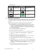
Dryer Safety Tags Tag Description Tag Read Operation & Installation Manual PE 1-2 Description High Voltage Inside Enclosure Hot! Lifting Point Protected Earth Ground Earth Ground Warnings and Precautions Our equipment is designed to provide safe and reliable operation when installed and operated within design specifications, following national and local safety codes. This may include, but is not limited to OSHA, NEC, CSA, SPI, and any other local, national and international regulations.
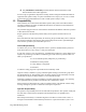
; Only PROPERLY TRAINED personnel familiar with the information in this manual should work on this equipment. We have long recognized the importance of safety and have designed and manufactured our equipment with operator safety as a prime consideration. We expect you, as a user, to abide by the foregoing recommendations in order to make operator safety a reality.
employer probably has established a set of safety rules in your workplace. Those rules, this manual, or any other safety information will not keep you from being injured while operating your equipment. Learn and always use safe operation. Cooperate with co-workers to promote safe practices. Immediately report any potentially dangerous situation to your supervisor. ; NEVER place your hands or any part of your body in any dangerous location.
When you need to perform maintenance or repair work on a dehumidifying dryer above floor level, use a solid platform or a hydraulic elevator. If there is a permanently installed catwalk on your dryer, use it. The work platform should have secure footing and a place for tools and parts. DO NOT climb on the dehumidifying dryer, machines, or work from ladders. If you need to repair a large component, use appropriate handling equipment.
Chapter 2: Functional Description 2-1 Models Covered in This Manual This manual provides operation, installation, and maintenance instructions for 600-3000 cfm Large Dehumidifying Dryers with AP1 control. These dryers are available with electric heaters or gas burners. Gas dryers are indicated with a “G” in the model number. Model numbers are listed on the serial tag. Make sure you know the model and serial number of your equipment before contacting the manufacturer for parts or service.
moisture is stripped from the air by a desiccant bed. The dried process air is then re-heated and delivered back into the drying hopper to dry material again. This system is a "closed loop", because ambient (outside) air is never introduced into the process air. The closed loop system is used by the manufacturer because the process air is typically much drier than ambient air, even after carrying moisture out of the plastic resin.
Once the main air valve and closed loop regeneration valve are in place, the process air blower starts. The system monitors the process air blower’s overload, starter auxiliary contact feedback and air pressure. Loss of any of these items when the process air blower is running will cause the process air blower and the drying hopper’s process heaters to shut down.
• Sequence shutdown switch ; NFPA86, UL, AGA & CGA machinery electrical standards (Gas Dryers) ; Available supply voltages of 208, 230, 460, 575/3/60 and 400/3/60 2-4 Options Dewpoint Extend The Dewpoint Extend option measures the temperature of the moist air as it is bled to the atmosphere after regeneration. After a period of time, the bleed temperature will rise. This condition, called "bed breakthrough" indicates that the bed is dry.
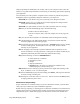
2-5 Drawings and Diagrams Regeneration Blower Insulated Drying Hopper Regen. Filter Process Air Filter Process Heater Optional Regeneration Closed Loop Cooler Regen. Optional Regeneration Exhaust Closed Loop Valve Optional After-cooler Right Desiccants Left Desiccants Dryer Valve Process Blower Airflow Schematic: 2000-3000 cfm dryers (4 desiccant beds). Left desiccant beds are regenerating—closed loop regeneration is activated. Regeneration Blower Regen.
Filter Check Gage Differential Pressure Switch Thumb Screws PS Cartridge Filter Dust Shroud Filter Retainer F E Slide Gate Clamp Dust Level Indicator Dust Pan Optional dryer dust collector Large Dehumidifying Dryers Functional Description 17
Process Aftercooler The optional aftercooler cools the moist air returning to the dryer from the drying hopper. The aftercooler can cool the return air from 250ºF to about 150ºF. This maintains the dryer’s efficiency and condenses the unwanted plasticizer from the air stream. The aftercooler requires a cooling water connection (see Figure and page 25).
Figure 4: Process Air Dust Collector Filter Check Gage Differential Pressure Switch Thumb Screws PS Cartridge Filter Dust Shroud Filter Retainer F E Slide Gate Clamp Dust Level Indicator Large Dehumidifying Dryers Dust Pan Functional Description 19
Material Overdrying Protection Material Overdrying Protection is an automatic system used to reduce the chance of overdrying, and possibly melting, the resin in the drying hopper. Material Overdrying Protection activates when the return temperature is above a set value, indicating that all the resin in the hopper is dry.
Mechanical Options ; Low temperature operation (120°F to 250°F) ; High temperature operation (250°F to 400°F) ; Precooler (Required for temperatures below 180°F, used with low temperature operation) ; Aftercooler (Required for temperatures above 250°F, used with high temperature operation) ; Plasticizer trap / Aftercooler w/filter ; Temperature Set Back ; Automatic airflow reduction valve (not for gas dryers) ; 13X desiccant ; Closed loop cooling valve ; Dew point +15°F to -80°F ; Sound insulation for under
2-6 Safety Devices and Interlocks This section includes information on safety devices and procedures that are inherent to the large dehumidifying dryer. This manual is not intended to supersede or alter safety standards established by the user of this equipment. Instead, the material contained in this section is recommended to supplement these procedures in order to provide a safer working environment.
In addition to the safety devices listed above, these dehumidifying dryers are equipped with a line cord plug. This allows the operator or maintenance personnel to unplug the system from its power source and tag it out. The plug can then be tagged with any number of approved electrical lockout tags available at most electrical supply stores. WARNING! Always disconnect and lockout all electrical power and pneumatic (i.e. compressed air) sources prior to servicing or cleaning the dehumidifying dryer.
9 Denotes availability Dimensions and Specifications CFM 600 850 1000 1250 1500 2000 2500 3000 (Electric Dryer w/ Basic Control) 9 9 9 9 9 9 9 9 (Electric Dryer High Performance) 9 9 9 9 9 9 9 9 (Gas Dryer option in lieu of Electric- 180°F to 250°F) 9 9 9 9 9 9 9 9 Gas dryer 250°F -400°F temp. range, includes aftercooler, 9 9 9 9 9 9 9 9 insulated drying hose, & high temp.
Electrical Features CFM Dryer AMP Draw 600 Standard voltage Low Heat (Electric Dryers) 208v/3/60Hz. 230v/3/60Hz. 400v/3/50Hz. 460v/3/60Hz. 575v/3/60Hz. Standard voltage High Heat (Electric Dryers) 208v/3/60Hz. 230v/3/60Hz. 400v/3/50Hz. 460v/3/60Hz. 575v/3/60Hz. Standard voltage (Gas Dryers) 208v/3/60Hz. 230v/3/60Hz. 400v/3/50Hz. 460v/3/60Hz. 575v/3/60Hz.
Chapter 3: Mechanical Installation 3-1 Uncrating the Equipment The large dehumidifying dryers are shipped mounted on a skid, enclosed in a plastic wrapper, and contained in a cardboard box. 1. Pry the crating away from the skid. Note: Remove the nails holding the box to the skid and lift the box off carefully; avoiding staples in the 1’ x 4’ wood supports. Cut the steel banding. 2. Use a pry bar to remove the blocks securing the unit to the skid. 3.
; Make sure all electrical connections are tight. 3-4 Making Gas Line Connections (Gas-Fired Models Only) Connect a gas line to the dryer’s gas inlet. See Figure 6 for a detailed schematic of the gas system.
3-5 Checking for Proper Blower Rotation After the electrical connections have been made, check the process and regeneration blowers for proper blower rotation. Check blower rotation before making process air connections between the dryer and hoppers, and before connecting cooling water (for the optional aftercooler). Blowers should rotate in a clockwise direction opposite shaft end. See Figure. The blowers are rotating properly when air flows from the delivery outlet.
3-6 Making Dryer/Drying Hopper Process Air Connections When making process air connections to your dryer, ensure that you take into consideration and make arrangements for the following: ; Use high-temperature flexible dryer hose or rigid tubing to connect the dryer to the drying hopper. ; Keep the delivery (to the drying hopper) hose as short as possible to minimize heat loss. Insulated hose is recommended and available for maximum energy savings.
Return air thermocouple location Process Air Heater on Drying Hopper Large Dehumidifying Dryers Mechanical Installation 30
Return air thermocouple location Drying System with Dust Collector and Process Air Heater on Dryer Large Dehumidifying Dryers Mechanical Installation 31
3-7 Connecting Aftercooler/Precooler Cooling Water (Optional) Support both sides of the fitting when making the cooling water connections to prevent damage to the aftercooler coil. See Figure. Connect 85°F water to the inlet closest to the exiting air side of the aftercooler coil. This will cool the process air about 100°F and raise the water-out temperature about 10°F. The table below lists available aftercooler models and their flow rates.
3-8 Using the Drying Hopper Air Trap Our exclusive air trap assembly in the top of the drying hopper prevents ambient air from contaminating the material being dried. To ensure that air does not enter the drying system, do the following (See Figure): ; Keep the material level above the bottom edge of the air trap for maximum efficiency. ; Use a hopper loader or vacuum conveying system to maintain the proper material level.
Chapter 4: Controls 4-1 Controller Description The AP1 control package uses a PLC with a touch screen interface to control the operation of the dryer. See for descriptions of each screen. Figure 11: Controller Screen Descriptions Main Menu. The main navigational screen. Used to access status and set-up screens. Dryer Status Screen. Displays actual dryer temperature and temperature setpoint, as well as actual dewpoint. Dryer Menu.
4-2 Identifying Control Panel Components for the AP-1 Optional Controller Disconnect Switch The Disconnect Switch is located in the front upper right hand corner of the control enclosure. It allows the user to disconnect power to the dryer for emergency shutdown, service or long periods of inactivity. Control Power Switch The Control Power Switch is located on the front of the control enclosure below the touch screen. The switch energizes the control circuit (PLC, touch screen, relays, etc.
• Copyright Information • PLC Version • Display Version After approximately 10-12 seconds the controller will flash to the Dryer Status Screen shown on the previous page. 4-4 Identifying Controller Screens Main Menu Screen (Main Menu Screen) The MAIN MENU provides information on the following system parameters: • • • • • DRYER ALARMS HELP SYSTEM LOG OFF Press the DRYER MENU button to return to the next section of dryer functions.
The DEW POINT value will give you a reading of what the actual process air dew point is. The area in the lower left portion of the touch screen conveys two lines of information relating to the overall operation of the dryer. The following is a list of typical machine/dryer summary status line text messages: 1. 2. 3. 4. 5. 6. 7. 8. 9. 10. 11. 12. 13. 14. 15. 16. 17. 18. 19.
Enter the values you would like to set in the screen by pressing the number keys. Press ENT (Enter) when you are finished to set the new values or CLR (Clear) to erase the current values and reenter new ones. To set the values in the next field, press ENT (Enter) to close the screen shown above. Then select the next number field to enter new values. For fields with a decimal point (X.X) enter the number assuming there is a decimal point present. For instance, to enter a 5.8 into an X.
By pressing the LOW TEMP or HIGH TEMP alarm buttons, the operator can enter the desired values to enable the alarm to go off at a specific deviation from setpoint (on the high or low side). When these settings have been made, the operator now has a choice of returning to the DRYER MENU or entering the MAIN MENU screen. (Dryer Setup Screen – 2 of 4) The dryer temperature values can be switched between reading in Fahrenheit and reading in Celsius.
OVERDRY PROTECTION (Overdry Protection Screen - 1 of 2) This feature is used to prevent the overdrying of the plastic resin in the drying hopper. RETURN TEMP provides the actual temperature of the process air leaving the drying hopper. Press the MORE button located in the top right corner of the Over-Dry Protection screen. By pressing the MATERIAL OVER-DRY OPTION button, the operator can enable or disable this feature.
ALARMS (Alarm History Screen) This screen allows the operator to review the number and type of issues that the dryer has encountered during its operation. Problems can be viewed by Date, Hour, and Comment. Because of the size of the screen, only three (3) comments/alarms can be viewed at a time. Alarm history is not resetable. (Display holds up to 100 messages). To view alarms not visible on the screen, press the DOWN button.
DEW POINT SETUP (Dew Point Setup Screen) This screen allows the operator to set the dew point. The HIGH DEW PT ALARM is an audible/visual alarm that will sound when the process air dewpoint rises to this value. Values can be set between –40 through +30 degrees. The dewpoint sensor only reads to a maximum of +15. Set the high alarm value to +30 to disable high dewpoint alarms. Used to configure the dewpoint switch. Regeneration will switch sides when the dewpoint reaches the switch value.
This button enables and disables the AutoStart Timer. HELP MENU (Help Menu Screen) The DRYER ALARMS button shows Help menus for Dryer Alarms. MAIN MENU (Main Menu Screen) This screen allows you to jump to the different areas of the controller to set, monitor, and operate different features of the dryer.
• • • SYSTEM BACKUP SERVICE MENU MAIN MENU SYSTEM SETUP (System Setup Screen) This screen allows the operator to set alarm and password features. ALARM OFF DUR is the amount of time (0-99 minutes) that the alarm and horn will stay off after the alarm silence button is pushed. (When this function is set to 0, this feature will never turn off. When it is set to 99, it will stay off until another alarm occurs.
The AP1 control system can detect and alarm a low material level condition in up to three (3) material hoppers. The material hopper assignments on the display are “Machine Hopper 1,” “Machine Hopper 2,” and “Drying Hopper.” Although your naming conventions may vary, the low material level detection capability of the AP1 can still be exploited. Refer to the provided electrical diagram for the proper wiring of the required level detection hardware.
Press the SYSTEM MENU button to return back to the system menu screen and the next set of programmable features. HOUR METERS (Hour Meter Screen) This screen monitors the number of hours that the dryer has operated. In addition to monitoring the total number of hours of equipment operation, it also has a resetable field that allows the operator to set the counter back to zero. This is useful for monitoring hours between equipment maintenance periods. Press the DRYER button to reset the counters.
(System Backup Screen) ACS Dryer control version 2.000 introduces a system backup feature. Pressing SAVE SETTINGS will save the system variables for later recall. Pressing RESTORE SETTINGS will restore previously saved values.
This service menu screen is PASSWORD PROTECTED and meant for ACS personnel use only. Press the RETURN key to go back to the SYSTEM MENU. Touching the MAIN MENU button in the SYSTEM MENU screen, will return the operator back to the overall menu screen. In this screen, the operator will be able to select the button that displays the ALARMS screen.
Alarm Screen Example This is an example of what a typical Alarm screen looks like. The user will see the message causing the alarm in the top half of the display with an ALARM SILENCE button in the lower half. To turn off the alarm, the user must press the ALARM SILENCE button. This will cancel the alarm. See Section 7-4: Alarms on p. 57 for alarm descriptions.
4-6 Setting the Redundant Safety Controller The Redundant Safety Controller alarm setting is changed by pressing the up and down keys to input the alarm value. The upper display reading indicates the Process Value, while the lower display indicates the High Point Setting alarm value. The factory setting for the High Point Alarm Value is 150°F (-23°C). Always put your set point to 30°F above set point. To set the redundant safety controller: 1. Press the P button. 2. The controller will ask for a password.
Large Dehumidifying Dryers Controls 51
Chapter 5: Operation 5-1 Start-up There are two possible methods of starting the dryer system: manually, by pressing the Start button on the Dryer Status screens, and automatically through use of the Auto Start Timer built into the dryer control system. Before operating the dryer, make sure all electrical connections are tight and that the blowers rotate in the right direction. Use the following procedure to start the dryer manually: 1. Close the slide gate at the bottom of the drying hopper. 2.
5-2 Using the Dryer Status Screen From the Main Menu screen, press the DRYER button to access the Dryer Status screen. The Dryer Status screen displays the set point and actual process temperature as well as the actual dewpoint. (Dryer Status Screen) The area in the lower left portion of the screen displays two lines of information relating to the overall operation of the dryer.
5-3 Alarms Use the Alarm History screen to monitor system alarms. From the Main Menu screen, press the Alarms button to access the Alarm History screen. The three most recent alarms appear at the top of the Alarm History screen. Use the DOWN and UP buttons to scroll through the alarms.
Alarm Comment REGEN LOW TEMP DEWPOINT SENSOR HIGH DEWPOINT PROCESS BLOWER FAIL PROCESS HEATER FAIL REGEN BLOWER FAIL REGEN HEATER FAIL DIRTY FILTER P RETURN SENSOR FAIL 5-5 Alarm Description Regeneration air temperature deviation is below low limit value. Possible heater failure. The dew point sensor is out of range. Possible transducer or electronics failure. The dew point value is above the high limit value. Faulty sensor or PC board. Possible ambient air contamination or failed regeneration cycle.
Chapter 6: Maintenance 6-1 Maintenance Schedule The checklist below contains a list of items that should be inspected and/or replaced to keep your Large Dehumidifying Dryer operating at peak efficiency. Perform each inspection at the regular intervals listed below.
6-2 Preventative Maintenance Cleaning or Replacing the Process Air Filters Regular filter cleaning will keep your dryer operating at peak efficiency. The process air filters protect the centrifugal blowers from plastic fines being drawn in from the drying hopper. Filters should be cleaned when airflow restriction trips the dirty filter alarm. Filters should be replaced at least once a year. Caution! Operating the dryer without the process air filters installed will void the warranty.
Use the following procedure to clean or replace the filter cartridges: 1. Turn off and/or lock out electrical power to the dryer. 2. Remove the hand knobs or clamps securing the filter access cover and remove the cover. 3. Remove the nut on the center retaining rod to remove a filter cartridge. 4. Vacuum, blow out, or wash the filter. 5. Inspect the filter - a damaged filter should not be reused.
5. Remove the restricted filter cartridge from the housing again. The alarm light should stay off when the process blower operates if the switch is adjusted correctly. 6. Re-install the obstructed cartridge filter. The alarm light should go on again if the switch is adjusted correctly. 7. Fine tune the switch setting so it consistently warns of a blocked filter and does not falsely indicate a blockage of a clean filter. 8. Remove the restriction from the filter element and re-install the clean filter.
6-3 Corrective Maintenance Symptoms of Worn Out Desiccant The moisture adsorption capacity of the desiccant used in Large Dehumidifying Dryers degrades after an indefinite period of time. Useful life depends on variables such as material moisture content, plasticizer vapors in the return air and number of regeneration cycles. Your dryer may need new desiccant if it exhibits any of the following symptoms: • The plastic material is not being dried sufficiently (high scrap/reject rate).
6. Inspect the gaskets on each of the covers. Replace if necessary. 7. Re-install the covers. Figure 14: Desiccant Tower Assembly Regeneration Heater Cover. High Temperature Gaskets. Regeneration Heaters Heater Element Mounting Plate. Viewing Glass, for checking the status of the desiccant inside. Access cover can be removed in order to replace desiccant. High Temperature Gaskets.
1. Remove the bolts securing the process heater access cover. 2. Sketch the heater wiring configuration so the heaters may be re-wired properly. Heaters are mounted on a common plate of three or six for easy maintenance. 3. Remove the jumper bars and wires for the heater plate assembly(ies) being removed or replaced. 4. Remove the bolts securing the heater plate assembly and slide out the assembly. Avoid damaging the gaskets. 5.
1. 2. 3. 4. 5. 6. Access the desiccant canisters by removing the panels on the dryer. Remove the Regeneration Heater Cover. Unscrew the six (6) screws on the Heater Element Mounting Plate. Slide out the heater assembly, taking care to not damage the gaskets. Unscrew the heater loops that need to be replaced. Re-install the new heaters. Securely tighten all fasteners. Caution! 7. 8. 9. 10. The heater loops should not touch each other. This will create "hot spots" and lead to premature heater failure.
Chapter 7: Troubleshooting 7-1 Introduction The utmost in safety precautions should be observed at all times when working on or around the machine and the electrical components. All normal trouble-shooting must be accomplished with the power off, line fuses removed, and with the machine tagged as out of service.
Problem Loss or reduction in drying capacity. Possible Cause Process heaters are faulty. Desiccant beds are contaminated. Material being dried differs from material specified at the time of purchase. Break in flex hose to/from drying hopper. Blower fins filled with dust or contaminants. Material in drying hopper cakes, or meltdown occurs. Process temperature set too high due to operator error. High temperature alarm not set properly. Process set point is out of acceptable range.
7-3 Determining Temperature Controller Errors or Sensor Errors Using a Thermocouple If the controller displays a temperature that is close to room temperature (70ºF/21ºC) when you short-circuit controller input terminals, the controller is normal and the sensor is probably broken, short-circuited, or incorrectly wired. Using a Platinum Resistance Thermometer If the controller displays a temperature of about 0.
Chapter 8: Appendix 8-1 Warranty The manufacturer warrants all equipment manufactured by it to be free from defects in workmanship and material when used under recommended conditions. The company’s obligation is limited to repair or replace FOB the factory any parts that are returned prepaid within one year of equipment shipment to the original purchaser, and which, in the company’s opinion, are defective. Any replacement part assumes the unused portion of this warranty.
8-2 Technical Specifications Annex B Information The following design information is provided for your reference: 1. No modifications are allowed to this equipment that could alter the CE compliance 2. Ambient temperature: 0 degrees Celsius – Maximum (104 degrees Fahrenheit) 3. Humidity range: 50% relative humidity 4. Altitude: Sea level 5. Environment: Clean and non-explosive 6. Radiation: None 7. Vibration: Minimal, i.e. machine mounting 8. Allowable voltage fluctuation: +/- 10% 9.
Large Dehumidifying Dryers 1000CFM 1000CFM 1000CFM 1250CFM 1250CFM 1250CFM 1250CFM 1250CFM 1500CFM 1500CFM 1500CFM 1500CFM 1500CFM 2000CFM 2000CFM 2000CFM 2500CFM 2500CFM 2500CFM 3000CFM 3000CFM 400V 50 HZ 3PH 460V 3PH 575V 60 HZ 3PH 208V 3PH 230V 3PH 400V 50 HZ 3PH 460V 3PH 575V 60 HZ 3PH 208V 3PH 230V 3PH 400V 50 HZ 3PH 460V 3PH 575V 60 HZ 3PH 400V 50 HZ 3PH 460V 3PH 575V 60 HZ 3PH 400V 50 HZ 3PH 460V 3PH 575V 60 HZ 3PH 400V 50 HZ 3PH 460V 3PH 3000CFM 1000CFM 2
LEVEL 3 ( Mechanical Components ) PART # SIZE Description A0542302 8" O.D. by 12 Ft Long Hi Temp Hose. A0571107 3" O.D. by 12 Ft Long Hi Temp Hose.
8-5 Dryer Identification (Serial Number) Tag (Located on back of Dryer) XXX Series Dryer Model Number XXX-15 Max Drying Capacity HR 460V Serial Number 060701R 1 Date of Manufacture 06/2003 4.5A Over-current Protection Device (s) 4.
8-5 Technical Assistance Parts Department Call toll-free 7am–5pm CST [800] 423-3183 or call [630] 595-1060, Fax [630] 475-7005 The ACS Customer Service Group will provide your company with genuine OEM quality parts manufactured to engineering design specifications, which will maximize your equipment’s performance and efficiency. To assist in expediting your phone or fax order, please have the model and serial number of your unit when you contact us.