
Wiring Instructions


steute Technologies GmbH & Co. KG
Brückenstraße 91, 32584 Löhne, Germany, www.steute.com
//
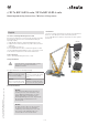
RF Tx NGF ULR2.4-safe / RF Rx NGF ULR2.4-safe
3 / 10
Mounting and wiring instructions / Wireless tilting sensor
English
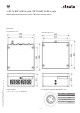
Installation
=
WARNING
Loose screws can cause parts to come loose
and fall off. Tighten all cover screws hand-tight.
The mechanical installation of the transmitter and receiver is the re-
sponsibility of the system operator.
The type of mounting and the mounting screws must be appropriate
for the intended application.
The maximum diameter of the bore hole is 6.5 mm.
During installation, ensure that no moisture penetrates the sensor.
Protection class IP65 is only achieved with a closed enclosure cover.
For correct wiring of the receiver, read the »Technical Data« chapter of
this manual.
Battery
=
WARNING
A wrong battery type may cause too short
runtimes, wrong voltage or make the batteries
not fit into the device. Use the NGF Tx with the
specified battery type only.
Do not mix old and new batteries. Make sure
that the battery charge lasts long enough for
the intended work.
Use four 1.5 V alkaline batteries, type D, specified for industrial use
(see technical data).
Battery insertion
Pairing
=
WARNING
If the receiver (Rx) is paired with a different
transmitter (Tx) than the intended one, the
measured hook tilt may be wrong. This may
lead to a dangerously inclined hook block.
Make sure that the installed set of NGF Tx and
Rx devices is paired correctly.
To have transmitter and receiver communicate with each other, pair
the devices once.
Before the pairing, make sure that the following conditions apply:
- Tx is powered up.
- Tx is in Idle Mode.
- Battery insulation strip has been removed.
- Enclosure cover has been removed.
- Rx is powered up.
- Rx is connected to the LSB bus interface.
- Rx and Tx are in radio range.