AV25-2-RS232 AV25-2 RS232 Owner’s Manual January 2012 www.stewartaudio.
Important Safety Instructions Before using your Stewart Audio Inc. Power Amplifier, please read this Owner’s Manual carefully to ensure optimum trouble-free performance. WARNING: TO REDUCE THE RISK OF ELECTRICAL SHOCK, DO NOT EXPOSE THIS AMPLIFIER TO RAIN OR MOISTURE. DANGEROUS HIGH VOLTAGES ARE PRESENT INSIDE THE ENCLOSURE. DO NOT OPEN THE CABINET. REFER SERVICING TO QUALIFIED PERSONNEL ONLY. CAUTION 3.
Table of Contents Important Safety Instructions······························································ 2 Table of Contents ················································································ 4 1 Welcome ························································································· 5 1.1 Features ··············································································· 5 1.
2.2.1 Universal-Mount Installation 2 Setup 2.1 Setup Precautions CAUTION: Before installing your amplifier, make sure that you have read the Important Safety Precautions at the beginning of this manual. The AV25-2-RS232 also has a universal bracket available which allows the unit to be mounted against a wall or under a table. Two screws are included in the kit which will affix the bracket to the top or the side of the unit. Once this is done, two holes are available for mounting the unit where desired.
2.2.3 Product Dimensions 2.4 Input Connections 4.25in 10.8cm 1.25in Your AV25-2-RS232 amplifier is provided with a 3-pin Phoenix connector for each input. This connector will accept both balanced or unbalanced connections, however some modifications must be made for an unbalanced connection. See the next two sections for instructions on connecting your amplifier to its input source. 3.2cm AV25-2-RS232 2.4.
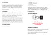
2.4.2 Unbalanced Connections 2.5 Output Connections When using an unbalanced input source and connector, a jumper must be added between the negative (-) terminals and the ground terminals. Once this has been done, the unbalanced source can be connected to the positive (+) and ground terminals. Diagrams have been provided for standard RCA and TS connectors. Please refer to the manual of your input source in case it does not follow the standard pin-out.
3 Operation 3.2 Controls, Indicators, and Connectors 3.1 Operating Precautions 4 5 #2 LEVEL - + - + PLENUM RATED #1 RX NOTE: Stewart Audio will not be held responsible for damage to your AV25-2-RS232 or connected equipment if the instructions in this manual are not followed. AV25-2-RS232 TX 1. Before use, your amplifier must be configure for proper operation, including input and output wiring hookup. Improper wiring can result in damage to equipment or potentially harm to the operator.
The AV 25 has 4 rear panel LED indicators. The first is the power indicator which will illuminate when power is supplied to the amplifier. The final light is the signal present LED which will illuminate when signal is detected on either one of the input connection channels. The final 2 LED indicators are the “Clip” indicators, one for each channel. These lights will indicate that the input signal is too “hot” and will sound distorted when amplified.
4.3 RS232 Commands 5 Troubleshooting Command Names and Description Hex Command VOLUME_UP Increases the volume by 10% 0x02 0x76 0x75 0x03 VOLUME_DOWN Decreases the volume by 10% 0x02 0x76 0x64 0x03 Problem: Power indicator does not turn on. Procedure: Check that the amplifier is plugged into a live outlet. After you have ensured that it is not a power issue, disconnect any speakers. If the amplifier turns on after a few seconds delay, then the problem is in the output connection.
This page intentionally left blank 6 Technical Specifications Maximum Output 30Hz - 20kHz Stereo 25W @ 8Ω per channel 35W @ 4Ω per channel Frequency Response (+0, -3 dB) 30Hz-20kHz Bandwidth +/- 3.0dB 30Hz-30kHz THD+N <0.1% Signal to noise ratio >100dB External Mute 5-12VDC Slew Rate 30V/ms Input Sensitivity 0.5V (-3 dBV) Standard Voltage Gain 28X (26.5dB) Input Impedance (Balance/Unbalanced) 20k Ohms/10k Ohms Sleep, Idle Current Draw, 1/8 Draw 0.005/0.01/0.
7 Warranty Information 7.1 Warranty Summary All Stewart Audio amplifiers and accessories, unless excluded in this summary, are covered by a 3-year limited warranty on parts and labor from the data of purchase. In order to be eligible for warranty repairs, the amplifiers and accessories must have been purchased through an authorized Stewart Audio dealer and submitted by the original purchaser. This warranty is only valid in the country in which the amplifier was purchased. 7.1.1 Eligibility Requirements.
7.2.3 Packaging Instructions (cont.) 1. Please write the RA number on three sides of the box. Include the Stewart Audio RA number inside the box and a brief description of the problem. 2. Do not ship any accessories (manuals, cords, hardware, etc.) with your unit. These items are not needed to service your product. Stewart Audio will not be held responsible for these items if they are returned with the amplifiers. 3. When shipping your amplifier, it is important that it has adequate protection.