4-Way ScreenWall ElectriMask O W N E R ’ S M A N U A L To the Owner Installation Instructions Operating the Screen Maintenance 4WSN-1005 T O T H E I N S TA L L E R : B E S U R E T O L E AV E T H I S M A N U A L W I T H T H E O W N E R .
Printed in U.S.A. ©2001-2005 Stewart Filmscreen Corporation Stewart Filmscreen reserves the right to make changes to the product specified in this document. From time to time, this document is updated. Current versions of documentation are posted on the Stewart Filmscreen website at www.stewartfilm.com.
4-Way ScreenWall ElectriMask O W N E R ’ S M A N U A L Contents To the Owner . . . . . . . . . . . . . . . . . . . . . . . . . . . . . . . . . . . . . . 2 Preparing the Installation . . . . . . . . . . . . . . . . . . . . . . . . . . . . . 4 Step 1. Mounting the Frame . . . . . . . . . . . . . . . . . . . . . . . . . . 5 Step 2. Electrical Hook-up . . . . . . . . . . . . . . . . . . . . . . . . . . . 10 Step 3. Hanging the Frame on the Wall . . . . . . . . . . . . . . . . 16 Operating the Mask . . . . . .
TO THE OWNER Congratulations on your purchase of the finest optical viewing screen available anywhere in the world! Please take a moment to review this manual—it will help ensure you many years of trouble-free service from your new Stewart Filmscreen product. About your 4-Way ScreenWall ElectriMask Your 4-Way ScreenWall ElectriMask is a fixed frame with both vertical and horizontal masking panels, enabling the viewer to obtain any aspect ratio.
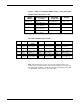
Figure 2: 4-Way ScreenWall ElectriMask models – sizes and weights Variable Format (from 2.35:1 to 4.3) Model Number NTSC Image Size 4:3/1.33:1 Attainable Image Size Weight 4WSNH100- 49” x 87” 124.5 x 221 cm Size Table: Row 1 130 lbs. / 59 kg 4WSNH110- 54” x 96” 137.2 x 243.8 cm Size Table: Row 2 140 lbs. / 63.5 kg 4WSNH123- 60” x 107” 152.4 x 271.8 cm Size Table: Row 3 150 lbs. / 68 kg 4WSNH135- 66” x 118” 167.6 x 300 cm Size Table: Row 4 160 lbs. / 72..
PREPARING THE INSTALLATION Before proceeding with the installation of this screen, take time to thoroughly read and understand these installation and operation instructions. All electrical wiring installations must conform to local and national codes and should be performed by qualified service personnel. There are no user-serviceable parts contained within the unit.
STEP 1. MOUNTING THE FRAME Professional mounting techniques should be used. Stewart Filmscreen Corporation cannot be liable for substandard or faulty installations. Assembling the frame Work in a clean area, making certain installers have clean hands and clothes. Assemble the frame on the floor. 1. Connect the four pieces by matching the colored numbered dots on the ends of the frame pieces. See Figure 3. 2. Secure with the supplied 1/2” (1.3 cm) Phillips pan head bolts.
Positioning the frame on the wall 1. Without the screen fabric attached, position the frame on the wall. 2. Make sure the unit is level and plumb. (You may need to use shims between the brackets and the wall to achieve vertical plumb). 3. Mark the position of the bracket holes on the wall. See Figure 4. Note: Later, when the screen fabric is attached to the frame (next section), you will hang the frame on the wall.
Unpacking and unrolling the screen The viewing side of the projection screen is rolled to the inside to protect the optical coating. The screen is rolled lengthwise. 1. Remove the screen from the cardboard shipping tube. 2. On a clean floor, unroll screen viewing side up. 3. Allow the paper to unroll between screen back and the floor. (This will keep the screen clean.) See Figure 5. Caution Be careful not to touch or scratch the image surface with fingernails.
Attaching the screen to frame 1. Place the frame over the screen. 2. While lifting the frame with one hand, snap the screen into the frame. Gently allow the screen to stretch onto the snaps. Do not jerk the material, as it can rip. See Figure 6. Attach the snaps on the top corners and top horizontal first, then lift the frame to a vertical position to finish attaching the rest of the snaps. Caution Do not use any tools to fasten the screen to the frame.
Connecting the spring tension cable 1. Locate the spring tension cables on either side of the unit. 2. Connect the baby eye snap to the eyelet on the lower bottom of the unit. See Figure 7. You will need to pull the cable slightly (about 10 lbs. / 4.5 kg of tension). 3. Repeat for the other side.
STEP 2. ELECTRICAL HOOK-UP Caution Professional techniques need to be used when making any electrical connection. A qualified electrician should perform these procedures. Be sure to follow all standard safety procedures for installing electrical devices. Do not disassemble or alter the configuration of the motor or the unit's electrical connections. This may cause injury to you or damage to the product. The electrical connection should be made only to the type of power source indicated on the marking label.
Installing the high voltage switch control (standard) A standard 3-position wall switch is supplied. The high-voltage control is connected to the electrical source. It alternates directions of mask motion by means of the hot lead, using the 3-position switch. Preparing the connection Before making the electrical connections, you need: An available AC constant power source A 4-conductor romex or motor connector cable (14 gauge recommended) Making the connections Figure 9 illustrates the connections.
Installing the low-voltage 3-button switch option The optional Stewart Filmscreen low-voltage control allows the use of lowvoltage wire to connect to the supplied 3-position momentary wall switch.
Installing the infrared remote control option The optional Stewart Filmscreen infrared remote control allows control of the screens from anywhere in the room. Note: The distance between the hand-held remote control and the receiver can be up to 50 feet / 15.2m. It is necessary to have uninterrupted line-ofsight between the remote and the receiver. Preparing the connection Refer to the previous section on “Installing the low voltage 3-button switch option.
Installing the Multi-Channel Infrared Remote control option The optional Stewart Filmscreen Multi-Channel Infrared Remote control allows control of the screens from anywhere in the room. Note: The distance between the hand-held remote control and the receiver can be up to 50 feet / 15 m. It is necessary to have uninterrupted line-ofsight between the remote and the receiver.
Connecting the Video Interface Control System (VICS) Note: The VICS option should not be used for the horizontal masking system. The VICS enables up and down operation of the mask in conjunction with a projector, tuner, VCR, cable box, or switched AC outlet. Preparing the connection Before making the electrical connections, you need: An available AC constant power source A 4-conductor cable (14ga) Making the connection Figure 13 illustrates the connections. 1.
STEP 3. HANGING THE FRAME ON THE WALL 1. Attach the ScreenWall ElectriMask to the wall using the appropriate fasteners (hex lag screws, wall anchors, molly bolts, wood carriage screws, etc.) through the wall mounting brackets.
OPERATING THE MASK The method you use to raise and lower a mask depends on the type of switch control device you have selected. When you lower or retract a mask, it will stop at its preset limit. Note: The horizontal masking panels move more slowly than the vertical masking panels. The slower motion allows you to adjust the image area with greater precision. The motor is designed to be used for short operations such as positioning the masks in preparation for viewing.
Modifying the extension of the mask 1 2 Horizontal Mask 3 4 You can increase the extension of a mask up to 3" / 7.6 cm past the factory preset stop, or you can decrease the extension from the factory preset stop. Do not attempt to modify a mask extension beyond these recommended amounts. Vertical Mask The limit switches are located on the head of the motor and can be accessed through openings located on the left side of the frame, as shown in Figure 15.
SCREEN CARE AND CLEANING With reasonable care, you can expect many years of trouble-free use of your Stewart projection screen. We encourage you to keep your screen clean. To protect your screen when it is not in use, store it in the fully retracted position. Avoid getting any foreign material on the screen, as cleaning may prove very difficult. It may not be possible to remove scratches, paint, ink, etc. General maintenance The surface of your screen is delicate.
TROUBLESHOOTING Refer to the following guidelines if you encounter a difficulty in the operation of your Stewart Filmscreen. Problems related to electrical or motor function may require a qualified service person or electrician. Should you have a problem that is not addressed here, call the Stewart Filmscreen Corporation. Problem description Mask won't operate. Probable cause No AC power available. Outboard switching problem. Action to take Check to see if the circuit breaker has switched off.
Problem description Probable cause Action to take Mask continues past bottom stop position. White limit switch is out of adjustment. Readjust the DOWN limit switch. Refer to figure 15. See pp. 17-18 of this manual. Batten retracts too far into frame. Yellow limit switch out of adjustment. Failure to correc t can damage motor and screen. Do not use the unit until this problem is resolved. Have a qualified se rvice person readjust the UP limit switch. Refer to Figure 15. See pp. 1 7-18 of this manual.
www.stewartfilm.