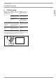
OPERATION AND INSTALLATION Electronically controlled instantaneous water heater »» DHB-E 13 AU »» DHB-E 18 AU »» DHB-E 27 AU electronic °C 40 35 30 45 50 55 60
CONTENTS | SPECIAL INFORMATION SPECIAL INFORMATION OPERATION 1. 1.1 1.2 1.3 General information �����������������������������������������3 Safety instructions ����������������������������������������������� 3 Other symbols in this documentation ����������������������� 3 Units of measurement ������������������������������������������ 3 2. 2.1 2.2 2.3 2.
OPERATION General information 1. 1.2 Other symbols in this documentation Note Notes are bordered by horizontal lines above and below the text. General information is identified by the symbol shown on the left. ff Read these texts carefully. General information The chapter "Operation" is intended for appliance users and qualified contractors. The chapter "Installation" is intended for qualified contractors.
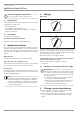
OPERATION Appliance description 4. Settings DHB-E 13 AU CE designation The CE designation shows that the appliance meets all essential requirements according to the: -- Low Voltage Directive -- Electromagnetic Compatibility Directive The maximum permissible mains impedance is indicated in chapter "Specification". 2.4 Test symbols 45 30 50 DHB-E 18 AU | DHB-E 27 AU See type plate on the appliance 35 Information for Australia/New Zealand: 30 Installation complies with standard AS/NZS 3500.4.
OPERATION Troubleshooting Troubleshooting Fault Cause The appliance will There is no voltage in the not start despite the appliance. DHW valve being fully open. The aerator in the tap or the shower head is scaled up or contaminated. The water supply has been interrupted. ENGLISH 6. Remedy Check the fuses/MCBs in your fuse box/distribution panel. Clean and/or descale the aerator or shower head.
INSTALLATION Safety INSTALLATION 7. Safety Only a qualified contractor should carry out installation, commissioning, maintenance and repair of the appliance. 7.1 General safety instructions We guarantee trouble-free function and operational reliability only if original accessories and spare parts intended for the appliance are used.
9.1 ! Installation site 10. Installation Material losses Only install the appliance in rooms free from the risk of frost. 10.1 Standard installation ff Always install the appliance vertically near the draw-off point. -- Electrical connection in the lower section of the appliance for installation on unfinished walls -- Water connection for installation on finished walls For further installation options, see chapter "Installation options".
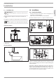
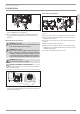
INSTALLATION Installation 160 1 26_02_02_0824_ 30 1 Installation aid ff Prepare the power cable. Note ff Install the flow limiter. ff With low water pressure.The pressure drop can be reduced by replacing the flow limiter with the plastic profile washer provided. Installing the appliance Preparing the water connection Material losses Carry out all water connection and installation work in accordance with regulations. D0000041720 ! D0000041721 26_02_02_1336 ff Remove the caps from the tees.
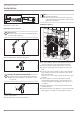
INSTALLATION Installation ff Screw the pre-assembled parts with flat gaskets to the cold water and DHW pipes of the appliance. ff Fit the cold water inlet pipe and the DHW outlet pipe from the pipework with flat gaskets to the extensions from the appliance. Making the electrical connection WARNING Electrocution Carry out all electrical connection and installation work in accordance with relevant regulations.
INSTALLATION Installation 10.2 Completing the installation 10.3 Installation options ff Open the shut-off valve in the cold water inlet line.
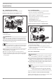
1. ! 2. Damage to the appliance and environment The strainer must be fitted for the appliance to function. ff When replacing the appliance, check that the strainer is present. ff Screw the connection pipes from the appliance to the tee. ff Open the shut-off valve in the cold water inlet line. 3. ff Before installing the appliance, use a screwdriver to push out the cable grommet. ff Slide the cable grommet over the power cable. For this, use the installation aid.
INSTALLATION Installation Temperature limitation / Anti-scalding protection Installation with offset tiles 20 1 D0000043278 110 2 1 Minimum contact area of the appliance 2 Maximum tile offset ff Adjust the wall clearance. Lock the back panel with the fixing toggle by turning it 90° clockwise. The maximum temperature can be limited to 43 °C via the programming unit on the appliance cover. For this, the following steps are necessary: ff Remove the appliance cover.
INSTALLATION Commissioning WARNING Electrocution Commissioning may only be carried out by a qualified contractor in accordance with safety regulations. ff Isolate all poles of the appliance from the power supply. ff Drain the appliance (see chapter "Maintenance"). 11.1 Initial start-up . 35 30 electronic °C 40 45 °C 50 40 55 35 60 30 45 50 2..
INSTALLATION Troubleshooting 13. Troubleshooting WARNING Electrocution In order to check the appliance it must be connected to the power supply. 13.1 Indicator options for LED diagnostic traffic light Indicator options Red Yellow Green Illuminates in the event of a fault Illuminates during heating mode Flashing: Appliance is supplied with mains power 13.2 Fault table Fault / diagnostic traffic light LED display The appliance does not start. Inadequate flow rate. The set temperature is not achieved.
INSTALLATION Maintenance WARNING Electrocution Before any work on the appliance, disconnect all poles from the power supply. ENGLISH 15. Specification 14. Maintenance 15.1 Dimensions and connections 225 140 ≤ 20 105 Draining the appliance You can drain the appliance for maintenance work. 478 b02 30 35 ff Close the shut-off valve in the cold water inlet line. ff Open all draw-off valves. ff Undo the water connections on the appliance.
INSTALLATION Specification 15.2 Wiring diagram 85_02_02_0005_ 3/PE ~ 380-415 V 1 Heater 2 High limit safety cut-out 3 Safety pressure limiter 15.3 DHW output DHW output is subject to the mains voltage, the appliance's connected load and the cold water inlet temperature. The rated voltage and rated output can be found on the type plate (see chapter "Troubleshooting"). Connected load in kW 38 °C DHW output in l/min. Rated voltage Cold water inlet temperature 380 V 400 V 415 V 5 °C 10 °C 15 °C 10.1 4.4 5.
INSTALLATION Specification ENGLISH 15.6 Fault conditions In case of faults, loads up to 95 °C at a pressure of 1.0 MPa can occur temporarily in the installation. 15.7 Data table DHB-E 13 AU 232360 Electrical data Rated voltage Rated output Rated current Fuse/MCB rating Phases Frequency Specific resistance ρ15 ≥ (at ϑcold ≤25 °C) Specific conductivity σ15 ≤ (at ϑcold ≤25 °C) Specific resistance ρ15 ≥ (at ϑcold ≤45 °C) Specific conductivity σ15 ≤ (at ϑcold ≤45 °C) Max. mains impedance at 50Hz Max.
WARR$NTY | ENVIRONMENT AND RECYCLING Warranty The warranty conditions of our German companies do not apply to appliances acquired outside of Germany. In countries where our subsidiaries sell our products, it is increasingly the case that warranties can only be issued by those subsidiaries. Such warranties are only granted if the subsidiary has issued its own terms of warranty. No other warranty will be granted.
12.4. The unit does not bear its original Serial Number or Rating Label. 12.5.
Deutschland STIEBEL ELTRON GmbH & Co. KG Dr.-Stiebel-Straße 33 | 37603 Holzminden Tel. 05531 702-0 | Fax 05531 702-480 info@stiebel-eltron.de www.stiebel-eltron.de Verkauf Tel. 05531 702-110 | Fax 05531 702-95108 | info-center@stiebel-eltron.de Kundendienst Tel. 05531 702-111 | Fax 05531 702-95890 | kundendienst@stiebel-eltron.de Ersatzteilverkauf Tel. 05531 702-120 | Fax 05531 702-95335 | ersatzteile@stiebel-eltron.de Australia STIEBEL ELTRON Australia Pty. Ltd.