
Operating Instructions and Installation Instructions

16 | DHB-E AU www.stiebel-eltron.com
INSTALLATION
Specication
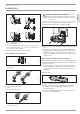
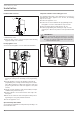
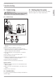
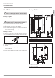
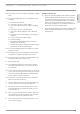
15.2 Wiring diagram
3/PE ~ 380-415 V
85�02�02�0005�
1 Heater
2 High limit safety cut-out
3 Safety pressure limiter
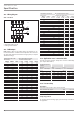
15.3 DHW output
DHW output is subject to the mains voltage, the appliance's con-
nected load and the cold water inlet temperature. The rated volt-
age and rated output can be found on the type plate (see chapter
"Troubleshooting").
Connected load in kW 38 °C DHW output in l/min.
Rated voltage Cold water inlet temperature
380 V 400 V 415 V 5°C 10°C 15°C 20°C
10.1 4.4 5.2 6.3 8.0
11.0 4.8 5.6 6.8 8.7
12.0 5.2 6.1 7.5 9.5
12.2 5.3 6.2 7.6 9.7
13.2 5.7 6.7 8.2 10.5
13.5 5.8 6.9 8.4 10.7
13.6 5.9 6.9 8.4 10.8
14.2 6.1 7.2 8.8 11.3
14.5 6.3 7.4 9.0 11.5
15.0 6.5 7.7 9.3 11.9
16.2 16.2 7.0 8.3 10.1 12.9
16.3 7.1 8.3 10.1 12.9
18.0 7.8 9.2 11.2 14.3
19.0 8.2 9.7 11.8 15.1
19.4 8.4 9.9 12.0 15.4
21.0 9.1 10.7 13.0 16.7
21.7 9.4 11.1 13.5 17.2
22.6 9.8 11.5 14.0 17.9
23.5 10.2 12.0 14.6 18.7
24.0 10.4 12.2 14.9 19.0
24.4 10.6 12.4 15.2 19.4
25.8 11.2 13.2 16.0 20.5
26.0 11.3 13.3 16.1 20.6
27.0 11.7 13.8 16.8 21.4
28.0 12.1 14.3 17.4 22.2
29.1 12.6 14.8 18.1 23.1
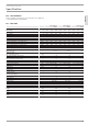
Connected load in kW 50 °C DHW output in l/min.
Rated voltage Cold water inlet temperature
380 V 400 V 415 V 5°C 10°C 15°C 20°C
10.1 3.2 3.6 4.1 4.8
11.0 3.5 3.9 4.5 5.2
12.0 3.8 4.3 4.9 5.7
12.2 3.9 4.4 5.0 5.8
13.2 4.2 4.7 5.4 6.3
13.5 4.3 4.8 5.5 6.4
13.6 4.3 4.9 5.6 6.5
14.2 4.5 5.1 5.8 6.8
14.5 4.6 5.2 5.9 6.9
15.0 4.8 5.4 6.1 7.1
16.2 16.2 5.1 5.8 6.6 7.7
16.3 5.2 5.8 6.7 7.8
18.0 5.7 6.4 7.3 8.6
19.0 6.0 6.8 7.8 9.0
19.4 6.2 6.9 7.9 9.2
21.0 6.7 7.5 8.6 10.0
21.7 6.9 7.8 8.9 10.3
22.6 7.2 8.1 9.2 10.8
23.5 7.5 8.4 9.6 11.2
24.0 7.6 8.6 9.8 11.4
24.4 7.7 8.7 10.0 11.6
25.8 8.2 9.2 10.5 12.3
26.0 8.3 9.3 10.6 12.4
27.0 8.6 9.6 11.0 12.9
28.0 8.9 10.0 11.4 13.3
29.1 9.2 10.4 11.9 13.9
15.4 Application areas/ conversion table
Specific electrical resistance and specific electrical conductivity
(see chapter "Data table").
Standard specifi-
cation
at 15 °C
20°C
25°C
Resist-
ance ρ
Conductivity σ Resist-
ance ρ
Conductivity σ Resist-
ance ρ
Conductivity σ
Ωcm mS/m μS/cm Ωcm mS/m μS/cm Ωcm mS/m μS/cm
900 111 1111 800 125 1250 735 136 1361
1000 100 1000 890 112 1124 815 123 1227
1100 91 909 970 103 1031 895 112 1117
1200 83 833 1070 93 935 985 102 1015
1300 77 769 1175 85 851 1072 93 933
15.5 Pressure drop
Taps/valves
Pressure drop at taps at flow rate of 10 l/min
Mono lever mixer tap, approx. MPa 0.04 - 0.08
Thermostatic valve, approx. MPa 0.03 - 0.05
Hand shower, approx. MPa 0.03 - 0.15
Sizing the pipework
To calculate pipework sizing, apply a pressure drop of 0.1MPa to
the appliance.