
Manual


15
English
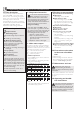
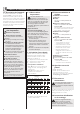
2.8 Water connection
# Install the supplied parts. Note the direc-
tion arrows of the water installation (
D
-
E
).
The three-way isolating valve (6) must
not be used to restrict the flow rate!
# Concealed connection
D
# Surface-type connection
E
The IP25 protection mode (hose-
proof) is guaranteed in the case of
the following connection.
1
2
3
4
5
6
7
8
10
11
12
13
14
15
16
17
18
19
20
21
22
23
24
9
With a Stiebel Eltron surface-type tap
fitting WKMD or WBMD (see ”2.12
Special Accessories”):
Use water plugs G ½ (23). Water plugs
fall within the scope of supply of the
Stiebel Eltron WKMD and WBMD fit-
tings.
In the case of third party tap fittings, the
special accessory module with 2 water
plugs (see ”2.12 Special accessories”) is
required.
1
2
3
4
5
6
7
8
10
11
12
13
14
15
16
17
18
19
20
21
22
23
24
9
In the case of surface-type installation
(see ”2.13 Special accessories”):
1. Use water plugs G ½ (24).
2. Use ½” union nuts with inlets for
Ø 12 mm diameter soldered joints (25).
Make a junction with 12 mm copper pipe
(25 a).
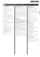
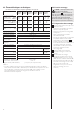
2.9 Electrical connection
F
The unit must be connected to the
protective earth terminal.
– In the case of concealed connection, the
power lead must protrude at least 30 mm,
with insulation, from the wall
G
.
– The cable pipe (
J
, 26) which is also
supplied must be used to provide a seal
against water penetration.
– Connect the connecting lead to the termi-
nal block.
– Priority circuit
H
DHF 13 C, DHF 15 C,
DHF 18 C, DHF 21 C, DHF 24 C:
when combined with other electrical
equipment, e.g. electric storage heaters,
the load-shedding relay should be used:
a Load-shedding relay (see ”2.12 Special
accessories”).
b Control line to switching relay of the
second unit (e.g. electrical storage
heater).
c Control contact, opens when the
DHF ... C compact control is switched
on.
Load shedding takes place when the
DHF ... C compact control is operated!
The load shedding relay may only be
connected to the middle phase
conductor of the unit terminal block.
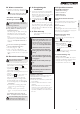
2.10 Completing the
installation
1. In the case of surface-type water installa-
tion and/or in the case of connection to
flexible water pipe systems, the rear panel
must be secured in the lower section
with an additional screw (
J
, 27).
2. Open the three-way isolating valve (
D
, 6).
3.
I
in the case of surface-type fitting
only:
Break out the pipe lead-through openings
(a) in the device cover cleanly, using a file
if necessary. The guide pieces (b) supplied
with the unit must be fitted into the lead-
through openings.
2.11 First start-up
(may only be carried out by a quali-
fied installer)
1
2
3
4
5
6
7
8
10
11
12
13
14
15
16
17
18
19
20
21
22
23
24
9
Fill and deaerate the unit. Note:
danger of running dry! Open a hot
water fitting downstream of the unit
until the cold water supply pipe and
the unit are free of air. With regard
to "air", see "1.3 Important notes".
1
2
3
4
5
6
7
8
10
11
12
13
14
15
16
17
18
19
20
21
22
23
24
9
Install the device cover and se-
cure with the screw. Insert the
locking cap and turn to the right
(lock).
1
2
3
4
5
6
7
8
10
11
12
13
14
15
16
17
18
19
20
21
22
23
24
9
Turn the output selector to the
left hand and the right hand stop,
to engage it.
1
2
3
4
5
6
7
8
10
11
12
13
14
15
16
17
18
19
20
21
22
23
24
9
Switch on the mains power sup-
ply.
1
2
3
4
5
6
7
8
10
11
12
13
14
15
16
17
18
19
20
21
22
23
24
9
Check the operating mode of the
instantaneous water heater.
1
2
3
4
5
6
7
8
10
11
12
13
14
15
16
17
18
19
20
21
22
23
24
9
Peel off the protective foil from
the control panel.
Handover of the unit!
Explain the function of the unit to the user
and familiarize him or her with its use.
Important instructions:
• Draw the user’s attention to possible haz-
ards (scalding).
• Hand over these instructions for careful
retention.
All the information set out in these in-
structions must be noted with the utmost
care. It provides guidance on the safety,
operation, installation, and maintenance of
the unit.
2.12 Special accessories
Twin-handle tap fittings
– WKMD kitchen fitting
Order no. 07 09 17
– WBMD bath fitting
Order no. 07 09 18
Grohe Relaxa shower hand-held
shower
Chrome plated plastic with particularly small
loss of pressure (0.2 bar at a flow rate of
10 l/min).
Order no. 06 85 21
Area of use:
A clearly higher flow rate is achieved in cases
where there is a particularly low supply pres-
sure in the water installation.
Module with 2 water plugs
Order no. 07 43 26
Required in the case of third party tap
fittings (
E
, 23).
Surface installation fitting set
Order no. 07 40 19
- Two water plugs G ½ (
E
, 24)
- Two ½” union nuts with inlays for
12 mm diameter soldered joints
(
E
, 25).
Not required in the case of Stiebel Eltron
WKMD and WBMD fittings.
LR 1-A load-shedding relay
Order no. 00 17 86
Priority circuit for the DHF ... C compact
control for simultaneous operation of, for
example, electric storage heaters.
For connection of the LR 1-A, see
H
.