
Instructions / Assembly


12 | SBB S & SBB PLUS SOLAR STORAGE TANKS WWW.STIEBEL-ELTRON-USA.COM
6
7
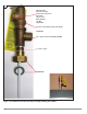
8.5 Hot water temperature probe
The hot water temperature probe is to be installed into the upper
immersions sleeve (Pos. 3, Figure 1).
8.6 Solar Storage Tank – Temperature Probe
The solar storage tank temperature probe to lower immersion sleeve
of the hot water storage tank (Pos. 6, Figure 1). The temperature
probe must be completely inserted into the probe sleeve.
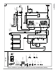
8.7 Connection to the Solar Unit
The installation of the solar loop is shown in Figures 4 & 5. The solar
loop must include temp/pressure relief, an air-vent, a check valve
and an expansion tank. Refer to the separate operation and installa-
tion instructions for the SOL 25 Plus fl at plate solar collector.
IMPORTANT NOTICE: TEST OPERATION AFTER INSTALLATION. START UP
MUST FOLLOW THE APPROVAL OF THE INSTALLER (REFER TO SECTION 3.
OPERATION AND SERVICE).
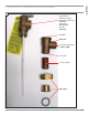
8.8 Sacrifi cial anode (spare part)
If a sacrifi cial anode is installed into the SBB S or SBB Plus storage
tank, the following must be observed:
Installation – sacrifi cial anode
• Pull out the red shut-off plug while simultaneously depressing the
pressure ring, (see Figure 7).
• Push in the open pipe end of the indicator element until dead-
stop.
• Attach the sticker “Note Signal Anode” to a highly visible spot on
the insulation.
NOTICE: WHEN THE STORAGE TANK IS NOT OPERATED WITH A SIGNAL
DISPLAY, THE RED PLUG MUST REMAIN IN THE ANODE.
Function – Sacrifi cial indicator
• After consumption of the anode, humidity escapes through the
hollow anode core to the signal cartridge and causes a color
change there (see Figure 7)
• When the cartridge turns red contact the installer so he can check
the anode and if needed replace it.
Routine maintenance improves operating safety and life
expectancy of the SBB S and SBB Plus solar hot water
storage tanks.
Figure 5: Temperature probe assembly
Figure 6: Sacrifi cial anode indicator