OPERATION AND INSTALLATION DHW heat pump »» »» »» »» WWK WWK WWK WWK 222 222 H 302 302 H
CONTENTS SPECIAL INFORMATION OPERATION 1. 1.1 1.2 1.3 General information �����������������������������������������4 Safety instructions ����������������������������������������������� 4 Other symbols in this documentation ����������������������� 4 Units of measurement ������������������������������������������ 4 2. 2.1 2.2 2.
SPECIAL INFORMATION -- The appliance may be used by children aged 8 and older and persons with reduced physical, sensory or mental capabilities or a lack of experience and know-how, provided that they are supervised or they have been instructed on how to use the appliance safely and have understood the resulting risks. Children must never play with the appliance. Children must never clean the appliance or perform user maintenance unless they are supervised.
OPERATION General information OPERATION 1. Symbol ! Meaning Material losses (appliance damage, consequential losses and environmental pollution) Appliance disposal General information The chapters "Special Information" and "Operation" are intended for both the user and qualified contractors. The chapter "Installation" is intended for qualified contractors. Note Read these instructions carefully before using the appliance and retain them for future reference.
WARNING Burns The water in the DHW cylinder can be heated to temperatures in excess of 60 °C. There is a risk of scalding at outlet temperatures in excess of 43 °C. ff Caution must be exercised when coming in contact with the water when discharged. WARNING Burns Touching hot components can lead to burns. ff When working on hot components, always wear protective working clothing and safety gloves. The pipework connected to the DHW outlet of the appliance can reach temperatures in excess of 60 °C.
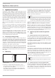
OPERATION Appliance description 3. Appliance description This appliance enables DHW to be supplied efficiently to several draw-off points using renewable energy. The appliance extracts heat from the ambient air. This heat is used to heat up the water in the DHW cylinder with added electric power. The amount of electrical energy and time required to heat up the hot water depend on the temperature of the air drawn in and the temperature of the water in the cylinder.
OPERATION Settings Frost protection The appliance activates the frost protection function if the integral sensor in the DHW cylinder captures a temperature below 8 °C. The appliance then heats the water by means of the heat pump and the electric emergency/booster heater. The heat pump and electric emergency/booster heater switch off when the temperature captured by the integral sensor reaches 16 °C. 3.
OPERATION Troubleshooting Protective anode and battery replacement The appliance is equipped with a maintenance-free impressed current anode that protects the cylinder from corrosion when it is connected to the power supply. At the factory, the appliance is fitted with rechargeable batteries that ensure the power supply to the impressed current anode in the case of a power failure. The power supply to the appliance must not be interrupted for more than 16 hours..
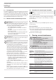
INSTALLATION 7. Safety Only a qualified contractor should carry out installation, commissioning, maintenance and repair of the appliance. 7.1 General safety instructions We guarantee trouble-free function and operational reliability only if original accessories and spare parts intended for the appliance are used. 7.2 9. Preparations 9.1 Transport ! Material losses The appliance has a high centre of gravity and low overturning moment. ff Safeguard the appliance against falling over.
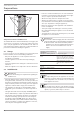
INSTALLATION Preparations 1 D0000034797 1 -- In the case of indoor installation, the size of the installation room must correspond to the application limits of the appliance (see chapter "Specification / Data table"). -- Observe the safety clearances and protection zones. -- Always leave sufficient space to provide access for installation, maintenance and cleaning. Observe the minimum clearances (see "Preparations / Siting the appliance").
Sound emissions The sound emissions are louder on the air intake and air discharge sides of the appliance than on the closed sides. ff Never direct the air intake or air discharge towards noise-sensitive rooms of the house, e.g. bedrooms. Note For details on sounds emissions, see chapter "Specification / Data table". 9.4 Siting the appliance ff Carefully undo the cardboard packaging at the clips. ! Material losses Take note of the appliance's weight and centre of gravity.
INSTALLATION Installation 10. Installation WARNING Injury Incorrect installation can lead to serious injury or material losses. Before any work, ensure sufficient clearances for the installation. Handle sharp-edged components carefully. 1 2 D0000063547 ! T&P valve (850 kPa) 10.1 Water connection ! Material losses Carry out all water connection and installation work in accordance with regulations.
INSTALLATION Installation 10.3 Power supply WARNING Electrocution The appliance is supplied with a flexible power cable without plug. In the case of a permanent connection, the appliance must be able to be separated from the power supply by an isolator that disconnects all poles with at least 3 mm contact separation. Contactors, circuit breakers or fuses can be used for this. This type of isolator must be installed in the fixed electrical installation according to the regulations.
INSTALLATION Installation ff If the connecting cable is not long enough, you may detach from the appliance and replace with a longer suitable cable, or extend connection as permitted by regional and national regulations (eg. use of a junction box). ff When routing the new power cable, ensure that it is waterproof as it passes through the existing cable grommet. Connect the connecting cable properly inside the appliance. 10.3.
INSTALLATION Installation Example 1: Power-OFF signal with its own phase The following diagram illustrates the connections by means of a sample signal sequence of an external signal transmitter. N Example: -- Water temperature = 62 °C -- Set temperature 1 = 61 °C -- Set temperature 2 = 65 °C L X0 GNYE PE PE PE BU N BN A 1 ENGLISH Following a one-off activation (signal is present for at least 1 minute), set temperature 2 applies for at least 20 minutes.
INSTALLATION Commissioning 10.4 Assembling the appliance Note Refit the appliance cover after completing your work. See chapter "Maintenance and cleaning / Fitting the appliance cover"). 11. Commissioning 11.1 Initial start-up Note Fill the DHW cylinder before switching on the power supply to the appliance. The appliance is equipped with boil-dry protection to prevent operation if the hot water cylinder is not completely full of water.
INSTALLATION Troubleshooting 13. Troubleshooting WARNING Electrocution Troubleshooting work must only be carried out by a qualified contractor. Prior to all work on the appliance, isolate it from the power supply. ! Material losses If you disconnect the appliance from the power supply, it is no longer protected against frost or corrosion. ff Only disconnect the appliance from the power supply for longer periods if you are also draining the DHW cylinder.
INSTALLATION Maintenance 14. Maintenance WARNING Electrocution Prior to all work on the appliance, isolate it from the power supply. D0000034803 14.1 Removing the appliance cover 1 D0000040621 1 Fixing screws on casing ring The casing ring is fastened with screws. ff Undo the fixing screws on the casing ring. ff Remove the condensate drain bend and pipe collar of the drain. Turn anti-clockwise to undo them. ! Material losses Inside the appliance, an earth cable is connected to the casing ring.
INSTALLATION Maintenance 14.4 Draining the cylinder WARNING Burns Hot water may escape when draining the DHW cylinder. To drain the DHW cylinder, e.g. when shutting the appliance down, proceed as follows. ff Isolate the appliance from the power supply. ff Close the shut-off valve in the cold water inlet line. The DHW cylinder is drained via the cold water supply line. ff Open the drain valve installed in the cold water supply line (see chapter "Water connection").
INSTALLATION Maintenance Material losses Never use batteries that cannot be charged. Only NiMH rechargeable batteries are permissible. Batteries may be damaged in the appliance. Without a power supply, the impressed current anode and the cylinder would not be protected against corrosion. ! The rechargeable batteries are secured at the back of the fascia. ff Open the battery compartment using a screwdriver. ff Replace the batteries (NiMH, type AAA, ≥ 800 mAh).
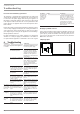
INSTALLATION Specification ENGLISH 15. Specification 15.1 Dimensions and connections 15.1.1 WWK 222 / WWK 222 H 690 g02 g01 b01 c06 c13 935 1160 1545 d45 i43 8-24 b01 c01 c06 c13 d45 g01 g02 i43 Entry electrical cables Cold water inlet DHW outlet T&P valve Condensate drain Air intake Air discharge Cover for manufacturing aperture www.stiebel-eltron.
INSTALLATION Specification 15.1.2 WWK 302 / WWK 302 H 690 g02 g01 b01 d45 c13 1287 1510 1913 c06 i43 8-24 218 c01 A A A A A D0000074178 30° A b01 c01 c06 c13 d45 g01 g02 i43 Entry electrical cables Cold water inlet DHW outlet T&P valve Condensate drain Air intake Air discharge Cover for manufacturing aperture 22 | WWK 222-302 H Male thread Male thread Female thread Male thread WWK 302 WWK 302 H G1 G1 Rp 3/4 G 3/4 G1 G1 Rp 3/4 G 3/4 www.stiebel-eltron.
INSTALLATION Specification ENGLISH 15.
INSTALLATION Specification A1 A3 C1 C2 E1 F1 F2 F3 F4 F5 G1 M1 M2 Electronic assembly (control unit) Electronic assembly (electrical corrosion protection) Run capacitor Rechargable battery pack Heating element High limit safety cut-out TSR Motor overload relay M1 High pressure switch Fuse Fuse, power supply, battery Impressed current anode Compressor Fan N1 R1 S1 S2 T1 T2 T3 T4 V1 V2 X0 X1 X3 X4 Thermostat TSR Resistance DIP switch (operating mode) DIP switch Cylinder top/integral temperature sensors Te
Versions IP rating Refrigerant Refrigerant charge Global warming potential of the refrigerant (GWP100) CO2 equivalent (CO2e) Power cable length approx. Dimensions Height Diameter Height when tilted Height when tilted incl. packaging Packing unit dimensions height/width/depth Weight Weight, empty Connections Condensate connection Safety valve connection Water connection WWK 222 WWK 222 H WWK 302 WWK 302 H t mm IP24 R134a 0.85 1430 1216 2000 IP24 R134a 0.85 1430 1216 2000 IP24 R134a 0.
GUARANTEE | ENVIRONMENT AND RECYCLING Warranty Stiebel Eltron Australia Only - According to national regulations in Australia 7. Warranty for Heat Pumps – Models WWK 222, WWK 222 H, WWK 302 and WWK 302 H Who gives the warranty 1. The warranty is given by Stiebel Eltron (Aust) Pty Ltd (A.B.N. 82 066 271 083) of 6 Prohasky Street, Port Melbourne, Victoria, 3207 ("we", "us" or "our").
Warranty exclusions 12. We may reject your warranty claim if: 14. You must ensure that access to the unit by our authorised service technician is safe and free from obstruction. 12.1. The unit was not installed by a registered and qualified plumber. 12.2. The unit was not installed and commissioned: 15. Our authorised service technician may refuse to inspect and test the unit until you provide safe and free access to it, at your cost.
Deutschland STIEBEL ELTRON GmbH & Co. KG Dr.-Stiebel-Straße 33 | 37603 Holzminden Tel. 05531 702-0 | Fax 05531 702-480 info@stiebel-eltron.de www.stiebel-eltron.de Verkauf Tel. 05531 702-110 | Fax 05531 702-95108 | info-center@stiebel-eltron.de Kundendienst Tel. 05531 702-111 | Fax 05531 702-95890 | kundendienst@stiebel-eltron.de Ersatzteilverkauf Tel. 05531 702-120 | Fax 05531 702-95335 | ersatzteile@stiebel-eltron.de Australia STIEBEL ELTRON Australia Pty. Ltd.