STIGA PARK 4WD 92 M 1 07 M 1 07 M H D 1 21 M 11 0 Comb i P r o 12 5 Comb i P r o 8211-0543-03
110/125 Combi Pro 1 125 Combi Pro 1 2 4 3 110/125 Combi Pro 121 M 107 M HD B C B A 110/125 Combi Pro 107 M HD 121 M 6 110/125 Combi Pro 5 110/125 Combi Pro Torx T30 E F Torx T30 8 121 M 7 121 M G H I 10 mm 2 10 mm
9 92/107 10 92/107 13 mm 13 mm 10 mm 11 92/107 M B D B A 12 92/107 M J K L 13 107 M HD 14 15 16 110/125 Combi Pro M 3
18 17 92/107 M 107 M HD 121 M 5 mm 20 19 110/125 Combi Pro 1/3 21 92/107 M 22 107 M HD 23 121 M 24 4
26 107 M HD 25 110/125 Combi Pro O O N 28 27 92/107 M 107 M HD 121 M P 24 Nm 125 Combi Pro 24 Nm 24 Nm Q 9,8 Nm 30 29 110 Combi Pro 45 Nm 5
EN ENGLISH 1 GENERAL This symbol indicates WARNING. Serious personal injury and/or damage to property may result if the instructions are not followed carefully. You must read these instructions for use and the machine’s safety instructions carefully. 1.1 Symbols The following symbols appear on the machine. They are there to remind you of the care and attention required in use. This is what the symbols mean: Warning! Read the instruction manual and the safety manual before using the machine.
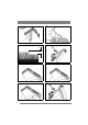
EN ENGLISH 2.3.3 Rear mounting The cutting deck’s rear section is secured with the pins in fig. 13. 2.4 Controls, 92/107 M 2.4.1 Cutting height adjustment The cutting height can be adjusted between 30 and 85 mm. The setting can be adjusted to a number of fixed positions using the lever. See fig. 9. 2.4.2 Incline forwards The cutting deck’s rear section can be raised infinitely variably. Each line (12:J) corresponds to a raise of 5 mm. The setting is locked with the screws (12:K). 2.4.
ENGLISH EN 3.2 Installation of 107 M HD, 121 M 3.3 Installing 92/107 M 1. Place the cutting deck in position in front of the machine. 2. Install the following components on both wheel axles: • Washer (3:B). • Deck mount (3:C). • Washer (3:B). • Circlip (3:A). 3. Remove the pins on both sides. See fig. 7:I and fig. 13. 4. Screw the arms into each other. See fig. 4. 5. Suspend the cutting deck in the implement lifter. See fig. 17. 6.
EN ENGLISH 3.5.2 Basic setting, 92/107 M, 121 M See fig. 17 and perform basic setting of 92/107 M and 121 M as follows: 1. Place the machine on a level floor. Requirements for floor flatness: ±1 mm/m. No slope towards a floor drain or similar may occur in front of or behind the machine. 2. The tyres must have the correct air pressure. See 3.4. 3. Place the deck in transport position and lay a plane-parallel plank under the deck. 4.
ENGLISH 5 MAINTENANCE 5.1 Preparation All service and all maintenance must be carried out on a stationary machine with the engine switched off. Prevent the machine from rolling by always applying the parking brake. Stop the engine. Prevent unintentional starting of the engine by disconnecting the spark plug cable from the spark plug and removing the ignition key. 5.2 Washing position 1. 2. 3. 4. EN 92/107 M: Lift up the rear section of the cutting deck, undo the catches (12:L) and lower.
EN ENGLISH 5.6.1 Separate blades The blades are replaceable. When replacing, both blades on the same blade bar must be replaced to avoid imbalance. Tightening torque: Screws (27:P) - 24 Nm Shear bolts (27:Q) - 9.8 Nm In the event of a collision, the shear bolts (27:Q) can break and the blades bend back. If this has happened, install genuine shear bolts and tighten as above. 5.6.2 Full blade, fig. 28-29 The full blade is replaced when the edges are worn.
w w w. s t i g a .