STIHL FS 91, 91 R 2 - 39 Instruction Manual
English 3 Your Dr. Nikolas Stihl 1 1.1 Guide to Using this Manual Pictograms The meanings of the pictograms attached to the machine are explained in this manual. Depending on the model concerned, the follow‐ ing pictograms may be attached to your machine.
2 Safety Precautions and Working Techniques English the design, engineering and appearance of our products periodically. If you have a pacemaker: The ignition system of your machine produces an electromagnetic field of very low intensity. This field may interfere with some pacemakers. STIHL recommends that per‐ sons with pacemakers consult their physician and the pacemaker manufacturer to reduce any health risk. Therefore, some changes, modifications and improvements may not be covered in this man‐ ual.
English 2 Safety Precautions and Working Techniques up and confine long hair above your shoulders. Wear safety boots with steel toe caps and non-slip soles. Sturdy shoes with non-slip shoes are permissible only when using mowing heads. WARNING To reduce the risk of eye injuries, wear close-fitting safety glasses in accordance with European Standard EN 166. Make sure the safety glasses are a snug fit. Wear face protection and make sure it is a good fit.
English 2 Safety Precautions and Working Techniques – Use only an approved combination of cutting attachment, deflector, handle and harness. All parts must be assembled properly and securely – The stop switch must be easy to push – Check the choke lever, throttle trigger and throttle trigger lockout for smooth action throttle trigger must return automatically to idle position.
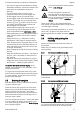
English 2 Safety Precautions and Working Techniques right hand on the control handle – even if you are left-handed. 2.7 While working Make sure you always have good balance and secure footing. In the event of impending danger or in an emer‐ gency, switch off the engine immediately by pressing the stop switch. 15m (50ft) There is a risk of accident from ejected objects within a wide area around the working area, so you must ensure that there is no-one within a 15 m radius of the machine.
2 Safety Precautions and Working Techniques Always shut off the engine before leaving the unit unattended. English 2.
English 2 Safety Precautions and Working Techniques No general recommendation can be given for the length of usage because it depends on several factors. The period of usage is prolonged by: – Hand protection (wearing warm gloves) – Work breaks The period of usage is shortened by: – Any personal tendency to suffer from poor cir‐ culation (symptoms: frequently cold fingers, tingling sensations). – Low outside temperatures. – The force with which the handles are held (a tight grip restricts circulation).
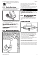
2 Safety Precautions and Working Techniques English Deflector must not be used with circu‐ lar saw blades. 2.13 Nylon line achieves a soft cut for edging and trimming around trees, fence posts, etc. – less risk of damaging tree bark. The mowing head comes with an instruction leaf‐ let. Refill the mowing head with nylon line as described in the instruction leaflet. Shoulder Strap/Harness The shoulder strap/harness is included with the machine or available as a special accessory.
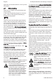
2 Safety Precautions and Working Techniques English 2.17 WARNING Grass Cutting Blade Never use wire in place of the nylon mowing line – risk of injury. 2.16 Risk of Kickout (Blade Thrust) with Metal Cutting Attachments WARNING 002BA135 KN 000BA020 KN When using metal cutting attach‐ ments there is a risk of kickout when the rotating blade comes into contact with a solid object such as a tree trunk, branch, tree stump, rock or similar.
2 Safety Precautions and Working Techniques English Before starting the cut, accelerate the engine up to full throttle. Perform cut with uniform pressure. Use circular saw blades only with a matching limit stop of the correct diameter. 002BA509 KN WARNING To cut wild growth and scrub, lower the brush knife down onto the growth to achieve a shred‐ ding effect – always keep the cutting attachment below hip level during this process. Exercise extreme caution when using this method of cutting.
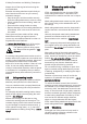
English 3 3 Approved Combinations of Cutting Attachment, Deflector, Handle and Harness Approved Combinations of Cutting Attachment, Deflector, Han‐ dle and Harness Cutting attachment Deflector, limit stop 1 2 3 4 Handle Carrying strap 19 14 20 23 25 24 25 24 25 21 16 6 7 8 15 22 20 9 10 17 18 13 3.
4 Approved Power Tool Attachments (Ø 250 mm) 13 Circular saw blade 200-22 chisel tooth (4112), circular saw blade 200-22 HP chisel tooth (4001) WARNING Grass cutting blades, brush knives and circular saw blades of other, non-metal materials must not be used. 3.3 Deflectors, limit stop 14 Deflector for mowing heads English Attachment SP 1) 4) SP 10 1) 5 5.
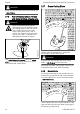
English 5.1.2 5 Mounting the Bike Handle Securing the Handlebar 5.1.3 Mounting the Control Handle A 12 ► Place the handlebar (7) in the lower clamp (1) so that distance A is no more than 15 cm (6 in). ► Place the upper clamp in position and hold both clamp moldings together. ► Push the wing screw through the two clamps as far as stop – hold all parts together and secure them.
5 Mounting the Bike Handle 5.1.4 English 5.1.6 Fitting the Throttle Cable Swiveling the Handlebar Transport position NOTICE Do not kink the throttle cable or lay it in tight radii – make sure the throttle trigger moves freely. 90° 3 15 14 14 15 ► Position the clamp (15) and handle sup‐ port (14) against the drive tube. ► Close the throttle cable retainer (15). The retainer (15) snaps into place. 5.1.
English 6 6.1 6 Mounting the Loop Handle Mounting the Loop Handle ► ► ► ► Position the clamp (6) against the drive tube. Place the barrier bar (2) in position as shown. Line up the holes. Insert the screws (7) in the holes and screw them into the barrier bar (2) as far as stop. ► Go to "Securing the Loop Handle". Mounting Loop Handle with Barrier Bar 6.
7 Adjusting the Throttle Cable Securing the Loop Handle 002BA655 KN 6.3 English A ► Set the throttle trigger to the full throttle posi‐ tion. ► Carefully rotate the screw in the throttle trigger in the direction of the arrow until you feel initial resistance. Then rotate it another half turn in the same direction. 4 9 002BA615 KN 8 8.
English 9 Mounting the deflector 9 Mounting the deflector 9.1 Mounting the Deflector 9.2 Fitting the Skirt and Blade WARNING Risk of injury from thrown objects and contact with the cutting attachment. These parts must be fitted to the deflector (1) when you use a mowing head. 1 9.3 3 Fitting the Skirt 002BA637 KN 2 002BA636 KN 3 ► Slide the lower guide slot of the skirt onto the deflector – it must snap into position. 9.
10 Mounting the Cutting Attachment 9.6 English Mounting the Limit Stop 7 3 002BA639 KN 6 2 Risk of injury from thrown objects and contact with the cutting attachment. Always fit the limit stop (6) when you use a circular saw blade. 1 ► Position the limit stop (6) on the gearbox flange. ► Insert the screws (7) and tighten them down firmly. 10 10.
English 10.3 10 Mounting the Cutting Attachment Blocking the Shaft ► Take the rider plate (4) off the shaft (5). Do not remove the thrust plate (6). 10.5 2 Mounting the Cutting Attach‐ ment 7 6 6 002BA330 KN WARNING The output shaft (2) must be blocked with the stop pin (6) or screwdriver (6) to mount or remove cutting attachments. These parts come standard with the machine or are available as special accessories.
10 Mounting the Cutting Attachment 10.8 English Mounting Metal Cutting Attach‐ ments Keep the leaflet and packaging of the metal cut‐ ting attachment in a safe place. 14 WARNING Wear protective gloves to reduce the risk of direct contact with the sharp cutting edges. 13 Mount only one metal cutting attachment. 10 Check direction of rotation of cutting attachment 8 11 3 1 12 2 4 ► Fit the thrust plate (9). ► Place the cutting attachment (8) on the thrust plate (9).
English 11 Fuel ► Remove cutting attachment and its mounting hardware from the gearbox – but do not remove the thrust plate (9). 11 Fuel Your engine requires a mixture of gasoline and engine oil. WARNING For health reasons, avoid direct skin contact with gasoline and avoid inhaling gasoline vapor. 11.1 STIHL MotoMix STIHL recommends the use of STIHL MotoMix. This ready-to-use fuel mix contains no benzol or lead, has a high octane rating and ensures that you always use the right mix ratio.
13 Fitting the Harness 12.1 English Preparations ► Turn the cap clockwise as far as stop and tighten it down as firmly as possible by hand. 13 Fitting the Harness 0000-GXX-0476-A0 The type and style of the harness/shoulder strap depend on the market. The use of the shoulder strap is described in the chapter on "Approved Combinations of Cutting Attachment, Deflector, Handle and Harness". 13.
English 13.2 14 Balancing the Machine 14 Full Harness 14.1 Balancing the Machine Attaching Machine to Harness 1 2 1 3 1 2 2 0000-GXX-0504-A0 1 002BA660 KN ► Put on the harness (1) and close the locking plate (3). ► Adjust the length of the strap – with the machine attached, the carabiner (2) must be about a hand's width below your right hip. ► Balance the machine – see "Balancing the Machine". 2 The type and style of the shoulder strap and car‐ abiner depend on the market.
English 002BA035 KN 14 Balancing the Machine B Circular saw blades (B) ► should "hover" about 20 cm (8 in) above the ground. When the correct balanced position has been reached: ► Tighten down the screw (1) on the carrying ring firmly. 002BA662 KN 2 1 ► ► ► ► ► 14.3 Disconnecting Machine from Harness Loosen the screw (1). Slide the carrying ring (2) along the drive tube. Tighten the screw (1) moderately. Allow the unit to hang freely.
English 15 15.1 15.1.1 15 Starting / Stopping the Engine Starting / Stopping the Engine ignition – see "Function of stop switch and ignition system". 15.1.3 Controls Version with Bike Handle Function of stop switch and ignition system The ignition is switched off and the engine stop‐ ped when the stop switch is pressed. The stop switch returns automatically to the Run position when it is released: The ignition is switched on again after the engine stops – the engine is then ready to start. 3 15.
15 Starting / Stopping the Engine 15.2.1 English ► Pull the starter grip slowly until you feel it engage and then give it a brisk strong pull. Cranking Do not pull out the starter rope all the way – it might otherwise break. ► Do not let the starter grip snap back. Guide it slowly back into the housing so that the starter rope can rewind properly. ► Continue cranking until the engine runs. 15.2.
English 15.4 16 Transporting the Unit Other Hints on Starting Engine stalls in cold start position g or under acceleration. ► Move the choke knob to < and continue cranking until the engine runs. 681BA269 KN Engine does not start in warm start position < ► Move the choke knob to g and continue cranking until the engine runs. If the engine does not start ► Check that all settings are correct. ► Check that there is fuel in the tank and refuel if necessary.
16 Transporting the Unit English 681BA275 KN 681BA269 KN 2. 1. Grass Cutting Blades up to 260 mm 2. 681BA311 KN ► Fit the transport guard on the cutting attach‐ ment from below. 681BA301 KN 16.4 681BA305 KN 681BA272 KN 681BA271 KN ► Disconnect wire rod from the transport guard. ► Swing wire rod outwards. ► Swing wire rod into position. ► Hook wire rod to the transport guard.
English 1. 681BA275 KN 2. ► Disconnect wire rod from the transport guard. 2. 681BA277 KN Circular Saw Blades 681BA302 KN 16.5 17 Operating Instructions ► Swing wire rod into position. ► Hook wire rod to the transport guard. 17 Operating Instructions 17.1 During break-in period A factory-new machine should not be run at high revs (full throttle off load) for the first three tank fillings. This avoids unnecessary high loads dur‐ ing the break-in period.
19 Adjusting the Carburetor 18.1 English If there is a noticeable loss of engine power 4 3 running and then turn the screw about another 1/2 to 3/4 turn in the same direction. WARNING 2 1 ► ► ► ► ► ► ► 0000-GXX-0482-A0 1 Turn the choke knob to g. Loosen the screws (1). Remove the filter cover (2). Clean away loose dirt from around the filter. Remove the filter element (3). Replace dirty or damaged filter element (3). Replace any damaged parts.
English 22 Engine Running Behavior ► Fit a new spark plug after about 100 operating hours – or sooner if the electrodes are badly eroded. Install only suppressed spark plugs of the type approved by STIHL – see "Specifica‐ tions". 21.1 Removing the Spark Plug 1 Arcing may occur if the adapter nut (1) is loose or missing. Working in an easily combustible or explosive atmosphere may cause a fire or an explosion. This can result result in serious inju‐ ries or damage to property.
24 Storing the Machine English ► Resharpen the teeth (1) uniformly – do not alter the contour of the parent blade (2) in any way. ► Insert the screw plug (1) and tighten it down firmly. 24 Storing the Machine For periods of 3 months or longer ► Drain and clean the fuel tank in a well ventila‐ ted area. ► Dispose of fuel properly in accordance with local environmental requirements. ► Run the engine until the carburetor is dry – this helps prevent the carburetor diaphragms stick‐ ing together.
English 26.3 26 Maintaining the Mowing Head Adjusting Nylon Line 26.4 Replacing Nylon Line STIHL SuperCut STIHL PolyCut Fresh line is advanced automatically if the remaining line is at least 6 cm (2 1/2 in) long. The blade on the deflector trims overlong lines to the correct length. Precut lengths of nylon line can be fitted to the PolyCut in place of the cutting blades. STIHL AutoCut ► With the engine running, hold the rotating mowing head above the grass surface.
27 Maintenance and Care Complete machine Control handle Air filter Visual inspection (condi‐ X tion, leaks) Clean Replace any damaged X parts Function test X Visual inspection Replace2) Manual fuel pump (if check X present) Have repaired by a spe‐ cialist dealer1) Fuel pickup body in fuel Have checked by tank dealer1) Have replaced by serv‐ icing dealer1) Fuel tank Clean Carburetor Check idle adjustment, X cutting attachment must not turn Adjust idle speed Spark plug Set electrode gap Replace after ever
Have replaced by serv‐ icing dealer1) Cutting attachment Visual inspection X X replace Check for secure fit X X Metal cutting attachment sharpen X Gearbox lubrication check X top up Safety information label replace 1)STIHL recommends STIHL dealers2)Only if there is a noticeable loss of engine power 28 Minimize Wear and Avoid Damage Observing the instructions in this manual helps reduce the risk of unnecessary wear and dam‐ age to the power tool.
29 Main Parts English – Mounting hardware for cutting attachments (rider plate, nut, etc.
English 30.2 31 Maintenance and Repairs Ignition System 30.7.2 Electronic magneto ignition Spark plug (resistor type): Bosch USR 7 AC Electrode gap: 0.5 mm 30.3 Fuel System All position diaphragm carburetor with integral fuel pump Fuel tank capacity: 30.4 710 cc (0.71 l) Weight Interchangeable Attachments The noise and vibration data of the approved attachments are listed in the instructions sup‐ plied with each attachment. The K‑factor in accordance with Directive 2006/42/EC is 2.
32 Disposal English STIHL recommends the use of original STIHL replacement parts. Directive 2000/14/EC, Annex V, and standard ISO 10884. Original STIHL parts can be identified by the STIHL part number, the { logo and the STIHL parts symbol K (the symbol may appear alone on small parts). Measured sound power level 32 108 dB(A) Disposal Observe all country-specific waste disposal rules and regulations. 106 dB(A) Guaranteed sound power level Technical documents deposited at: ANDREAS STIHL AG & Co.
0458-426-8321-B *04584268321B* www.stihl.