STIH) STIHL Series 4144 Components FC, FS, KM 2008-02 FS 40, FS 50, FS 56 FC 56 KM 56
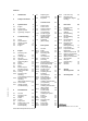
Contents 1. Introduction 2 6.7 6.8 2. Safety Precautions 3 3. Specifications 4 3.1 3.2 3.3 3.4 Engine Fuel System Ignition System Tightening Torquese 4 4 4 5 7. Control Levers 7.1 Switch Shaft / Control Lever Switch Positions Interlock Lever (Loop Handle) Throttle Trigger Throttle Trigger/ Interlock Lever (Bike Handle) Handlebar (Bike Handle) 7.2 7.3 7.3.1 7.4 4. Troubleshooting 4.1 4.2 4.3 4.4 4.5 Clutch Rewind Starter Ignition System Carburetor Engine 5. 5.1 5.2 5.3 5.4 5.5 5.6 5.
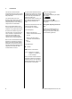
1. Introduction This service manual contains detailed descriptions of all the repair and servicing procedures specific to this power tool. You should make use of the illustrated parts lists while carrying out repair work. They show the installed positions of the individual components and assemblies. Refer to the latest edition of the relevant parts list to check the part numbers of any replacement parts.
2. Safety Precautions If the engine is started up in the course of repairs or maintenance work, observe all local and countryspecific safety regulations as well as the safety precautions and warnings in the instruction manual. Gasoline is an extremely flammable fuel and can be explosive in certain conditions. Always wear suitable protective gloves for operations in which components are heated for assembly or disassembly. Improper handling may result in burns or other serious injuries.
3. Specifications 3.1 Engine Displacement: Bore: Stroke: Engine power to ISO 8893: Max. permissible speed (with cutting attachment): Idle speed: Clutch: Clutch engages at: Crankcase leakage test at gauge pressure: under vacuum: 3.2 FS 40 FS 50, 56, FC 56, KM 56 27.2 cm3 34 mm 30 mm 0.7 kW (1.0 bhp) at 8,500 rpm 27.2 cm3 34 mm 30 mm 0.8 kW (1.1 bhp) at 8,500 rpm 10,000 rpm 2,800 rpm Centrifugal clutch without linings 4,200 rpm 10,000 rpm 2,800 rpm Centrifugal clutch without linings 4,200 rpm 0.
3.4 Tightening Torquese DG and P (Plastoform) screws are used in polymer and light metal components. These screws form a permanent thread when they are installed for the first time. They can be removed and installed as often as necessary without impairing the strength of the screwed assembly, providing the specified tightening torque is observed. For this reason it is essential to use a torque wrench.
Remarks: 1) Loctite 242 or 243, medium strength 2) Loctite 270, high strength 3) Loctite 649, high strength 4) Loctite 272, high strength up to 250°C 5) Degrease crankshaft/flywheel and mount oil-free Use the following procedure when refitting a DG or P screw in an existing thread: Place the screw in the hole and rotate it counterclockwise until it drops down slightly. Tighten the screw clockwise to the specified torque.
4. Troubleshooting 4.
4.2 Rewind Starter Condition Cause Remedy Starter rope broken Rope pulled out too vigorously as far as stop or over edge, i.e.
4.3 Ignition System Exercise extreme caution while carrying out maintenance and repair work on the ignition system. The high voltages which occur can cause serious or fatal accidents. Condition Cause Remedy Engine runs roughly, misfires, temporary loss of power Spark plug boot is loose Press boot firmly onto spark plug and fit new spring if necessary Spark plug sooted, smeared with oil Clean the spark plug or replace if necessary.
Condition Cause Remedy No spark Spark plug faulty Install new spark plug Faulty insulation or short in short circuit wire Check short circuit wire for short circuit to ground Break in ignition lead or insulation damaged Check ignition lead, replace ignition module if necessary Ignition module faulty Install new ignition module 10 Series 4144 Components FC, FS, KM
4.
Condition Cause Remedy Engine will not idle, idle speed too high Throttle shutter opened too wide by idle speed screw LA Reset idle speed screw LA correctly Oil seals/crankcase leaking Seal or replace oil seals/crankcase Idle jet bores or ports blocked Clean the carburetor Setting of low speed screw too rich or too lean Reset low speed screw L correctly Setting of idle speed screw LA incorrect – throttle shutter completely closed Reset idle speed screw LA correctly Tank vent faulty Replace ta
Condition Cause Remedy Engine speed drops quickly under load – low power Air filter dirty Clean air filter or replace if necessary Throttle shutter not opened fully Check throttle cable and cable adjustment and readjust if necessary Tank vent faulty Replace tank vent Fuel pickup body dirty Install new pickup body Fuel strainer dirty Clean fuel strainer in carburetor, replace if necessary Leak in fuel hose between tank and fuel pump Install new hose Setting of high speed screw H too rich Che
4.
5. Engine 5.1 Removing and Installing 1 1 – Remove the drive tube, b 9.1 : Pull the protective cap (1) off the spark plug boot (2). 545RA029 TG 2 938RA087 TG – Remove the rewind starter, b 6.2 2 : Disconnect the short circuit wire (1) and ground wire (2). 545RA025 TG 1 – Push the boot on to the spark plug. : Take out the screw (arrow). 545RA030 TG – Remove the filter cover (1). 1 545RA027 TG 1 : Disconnect the tank vent hose (1) from the filter housing (arrow).
Installing 1 : Turn the pin (2) until the slot is in line with the throttle cable (1). : Remove the air baffle (1). – Inspect the muffler and replace if necessary, b 5.8 – Check the air filter, carburetor and spacer flange, replace as necessary, b 8.1, b 8.2, b 8.7 – Remove the throttle cable (1). 545RA035 TG – Press down the throttle lever until the nipple (arrow) projects.
1 1 2 : Insert screws (arrows) and tighten them down firmly. 545RA043 TG – Check operation – squeeze throttle trigger on handle as far as stop. The throttle shutter must be fully open, adjust throttle cable if necessary, b 8.6.2 545RA041 TG 1 – Turn the machine over. – Fit throttle cable (1) in the pin's (2) slot. : Turn the pin until the nipple is properly seated (arrow). : Install new fuel return hose (1) and fuel suction hose (2), b 8.9.
1 : Insert the screws (1) – do not tighten them down yet. 1 2 – Reassemble all other parts in the reverse sequence. 545RA048 TG 545RA045 TG – Tightening torques, b 3.4 1 : Push short circuit wire (1) and ground wire (2) firmly onto the connector tags. : Place the shroud (1) in position behind the air baffle (arrows). 545RA290 TG – Push the shroud (1) down until it engages the locking tabs. 545RA062 TG : Push on the protective cap (1) as far as stop.
5.8 Muffler / Spark Arresting Screen Always check and, if necessary, repair the fuel system, carburetor, air filter and ignition system before looking for faults on the engine. Spark arresting screen (if fitted) 1 – Troubleshooting, b 4.5 545RA052 TG – Remove the rewind starter, b 6.2 545RA055 TG 1 – Remove the drive tube, b 9.1 – Remove the shroud, b 5.1 Use a new exhaust gasket. – Insert the screws. : Take out the screw (arrow) and remove the spark arresting screen (1).
5.9 Short Circuit Wire 5.9.1 Testing To locate the fault, test the wires for continuity and check insulation for damage. If the wires are in order, check operation of stop switch, b 5.10 1 1 2 545RA058 TG If no fault can be found, check the ignition system with the aid of the troubleshooting chart, b 5.10. If the spark plug, ignition lead and spark plug boot are in order, check the short circuit wire. – Remove the shroud, b 5.1 : Disconnect the short circuit wire (1).
– Push the flag terminals firmly on to the connector tags of the stop switch. 2 : Push the flag terminal of the short circuit wire (1) onto the rear connector tag (see illustration). 1 545RA063 TG 1 545RA061 TG 3 : Squeeze the retaining tabs (arrows) together and push the stop switch (1) out of the support. : Disconnect the short circuit wire (1) and ground wire (2) from the stop switch (3). – Take the wires and stop switch out of the support. – Check the individual parts and replace if necessary.
1 2 545RA070 TG : Fit the wires, ground wire (1) first, in the guide – position the wires next to one another without loops. : Push the support fully home and position the wires, short circuit wire first, in the guide (arrow). 545RA045 TG 545RA067 TG 1 : Push short circuit wire (1) and ground wire (2) firmly onto the connector tags. – Reassemble all other parts in the reverse sequence. – Tightening torques, b 3.4 – Check operation.
5.9.3 Removing and Installing (Bike Handle Version) 1 2 The short circuit wire (black), ground wire (blue) and throttle cable are in a protective tube. : Disconnect the short circuit wire (1) and ground wire (2). 545RA073 TG 1 545RA075 TG 545RA058 TG 1 : Pull the ground and short circuit wires with throttle cable out of the guides (arrows). : Pull the short circuit wire out of the guide (arrow). : Take out the screw (arrow) and remove the lock nut. 1 545RA072 TG – Remove the drive tube, b 9.
1 – Remove the handle molding and levers, b 7.4 : Disconnect the wires from the stop switch. 545RA083 TG – Tie a thin piece of string to the straight terminal on the short circuit wire (1). : Pull short circuit wire (1) out of the protective tube (2) in direction of throttle cable retainer (3) and undo the string. 1 3 1 2 – Check the short circuit wire and replace if necessary. 545RA082 TG 545RA079 TG 2 : Pull the protective tube (1) out of its seat (arrow) in the handle molding.
– Thread the short circuit and ground wires through the hole (arrow) in the handle molding. 1 2 545RA088 TG 545RA085 TG 1 : Push the protective tube (1) and throttle cable (2) into their seats (arrows) in the handle molding. 545RA090 TG Installing – Fit the handle molding (1) in position. : Insert screws (arrows) and tighten them down firmly. 1 1 1 545RA086 TG 2 : Position the stop switch (1) so that the lug (2) engages the slot (arrow) in the opening.
5.9.4 1 Ground Wire A faulty ground wire may impair or prevent operation of the short circuit wire. 545RA071 TG 545RA281 TG 1 : Fit the short circuit wire (1) in the guide (arrow). – Position the protective tube (1) against the engine housing. 1 – Check for contact and continuity and replace ground wire if necessary, b 5.9.1 2 545RA045 TG : Press the protective tube (1) into its seat (arrow) as far as stop – it is now secure.
5.10 Ignition System Troubleshooting Troubleshooting can be performed with the engine installed. Refer to service manuals of "Series 4144 Powerhead" or "Series 4144 Components – FS, FC, KM" for descriptions of procedures.
1 Powerful spark? yes no Air gap: – Check ignition module/flywheel, – adjust if necessary, see "Series 4144 Check the flywheel: – Have pole shoes turned blue? – install new flywheel if necessary, see "Series 4144 Powerhead" Check short circuit wire: – Wire damaged? – Connectors firmly seated? – Check the short circuit wire for break and replace if necessary, b 5.9 Check the ignition lead: – Severe chafing? – Spark plug boot: Holes/cracks? – Resistance: spark plug boot to ground: spec. 1.
2 3 Check stop switch: – Short circuit wire chafed? – Operation of stop switch: – Idle position = no connection – Position "0" = connection – Install new short circuit wire if necessary, b 5.
6.1 General If the action of the starter rope becomes very stiff and the rope rewinds very slowly or not completely, it can be assumed that the starter mechanism is in order but plugged with dirt. At very low outside temperatures the lubricating oil on the rewind spring may thicken and cause the spring windings to stick together. This has a detrimental effect on the function of the starter mechanism.
1 3 : Fit the torsion spring (1) so that its leg (arrow) is against the pawl. The torsion spring must be pushed fully onto the locking peg (2). Pawls have locking pegs and guide pegs (3). 1 : Leg (arrow) of torsion spring must be preloaded and locate against the carrier. – Pull the boot off the spark plug. – Check operation. : Block the piston with the locking strip (1) 0000 893 5904. Spring force must move the pawls in the direction of the carrier's hexagon – as far as stop.
6.4 Rope Rotor 2 – Remove the starter rope or remaining rope from the rotor, b 6.5 A new rope rotor comes with the rewind spring and ErgoStart spring preassembled. – Check the rope rotor and replace if necessary. All models 1 545RA105 TG A new rope rotor comes with the rewind spring preassembled. Relieving tension of rewind spring – Coat bore in rope rotor with STIHL special lubricant, b 11 Models with ErgoStart The rope rotor accommodates the ErgoStart spring and rewind spring.
6.5 Starter Rope / Grip Models with ErgoStart – Remove the rewind starter, b 6.2 2 1 The system will not be under tension if the starter rope is broken. 545RA114 TG 545RA284 TG – Relieve tension of rewind spring, b 6.6 : Fit the E-clip (arrow). – Remove the rope rotor, b 6.4 Models with ErgoStart – Remove remaining rope from the rope rotor and starter grip. : Push the end of the starter rope (1) out a little and undo the knot. Do not shorten the starter rope.
– Pull any remaining rope out of the sleeve. Inspect the individual parts and replace if necessary. Do not shorten the starter rope. – Thread the rope through the top of the starter grip. 545RA115 TG 296RA151 TG 1 1 : Thread the starter rope (1) through the guide bushing (arrow). 545RA285 TG : Pull the rope with knot into the starter grip until it is properly seated in the grip (small arrow). – Tie a simple overhand knot in the end of the new rope and thread the rope through the sleeve.
Models with ErgoStart 6.6 Tensioning the Rewind Spring 1 2 2 1 3 – Remove the rewind starter, b 6.2 545RA119 TG : Pull out the twisted rope (1) with the starter grip and straighten it out. – Use the hook (2) 5910 890 2800 to pull out the starter rope (1) from between the rope rotor and housing and engage it in the rotor's notch (arrow). : Use the starter rope (1) to rotate the rope rotor (3) six turns clockwise, : Pull the rope back until the knot locates in the recess (arrow) in the rope rotor.
A replacement spring is supplied ready to install with a new rope rotor. The rewind spring is correctly tensioned when the starter grip sits firmly in the rope guide bushing (arrow) without drooping to one side. If this is not the case, tension the spring by one additional turn. – Remove the rope rotor, b 6.4 – Secure the spring so that it cannot pop out. 1 : If necessary, line up the inner spring loop (arrow) so that it is against the edge of the rope rotor.
Control Levers 7.1 Switch Shaft / Control Lever 7.2 Switch Positions – Position < = warm start – warm engine is started in this position. 2 – Position g = cold start – cold engine is started in this position On these machines the operating modes are set on the handle and the carburetor: 7.3 On the handle 545RA128 TG 7. 1 Interlock Lever (Loop Handle) : Remove the torsion spring (1). – Check the interlock lever (2) and torsion spring (1) and replace if necessary 1 1 – Remove the shroud, b 5.
1 : Fit the torsion spring (1) in the interlock lever so that its leg (arrow) engages the recess as shown (arrow). 1 : Press the interlock lever (1) into the mounts until it snaps into place. 545RA135 TG : Disconnect the throttle cable (1). – The leg of the torsion spring must locate against the edge (arrow) of the support and project slightly. 2 1 – Install the support and fit the short circuit wire in the guide, b 5.9.
2 1 – Check the grub screw (1) and throttle trigger (2) and replace if necessary Make sure the grub screw (1) is in place. – Fit the lever on the same side as the grub screw. : Push the lever (1) onto the pivot pin so that the lug is below the shoulder (arrow). 545RA143 TG 2 545RA140 TG 1 545RA138 TG 1 2 : Press the throttle trigger (1) into the mounts until it snaps into place. The leg (2) of the torsion spring must locate against the edge (arrow) and project slightly.
1 1 – Check operation. : Take out the screws (arrows). The throttle trigger must be locked in position when the interlock lever is not depressed. – Remove the handle molding (1). : Release the throttle trigger – it must return to the stop : Carefully remove the interlock lever (1) – tension of torsion spring (2) is suddenly relieved. – Remove the torsion spring (2). 1 – Reassemble all other parts in the reverse sequence.
2 : Push the interlock lever (1) into position and engage the torsion spring (arrow). – Check that the stub (1) is in place, fit a new grub screw if necessary. 545RA156 TG 1 545RA154 TG 545RA152 TG 1 1 – Push the throttle trigger (1) onto the pivot pin. : Turn the interlock lever (2) slightly and continue pushing the throttle trigger into position until it engages the interlock lever. A new throttle trigger comes with the grub screw fitted.
: Release the throttle trigger (2) – it must return to the stop 1 : Push the throttle cable (1) and protective tube (2) into the seats (arrows) and hold in that position. 2 545RA163 TG : Fit the torsion spring (1) on the throttle trigger and attach its loop to the boss (arrow). 2 545RA162 TG 1 545RA159 TG 1 – Line up the control handle (1) so that the throttle trigger points towards the coupling sleeve. 1 : Rotate the leg clockwise and engage it on the lever (arrow).
7.5 Handlebar (Bike Handle) 545RA165 TG – Line up the handle so that its long side (arrow) faces the cutting tool. The handle must be fitted in the dry condition. : Push the handle on to the handlebar as far as stop. : Take out the screws (arrows). Handlebar and lower clamp drop down after the screws have been removed. 545RA169 TG 545RA167 TG – Remove the control handle, b 5.9.3 1 – Position the preassembled handlebar on the drive tube.
8. Fuel System 8.1 Air Filter 8.1.1 Dirty air filters reduce engine power, increase fuel consumption and make starting more difficult. The air filter should be checked when there is a noticeable loss of engine power. Baffle 8.1.2 Remove the air filter, b 8.1 Filter housing Remove the air filter, b 8.1 – See also troubleshooting, b 4.4, b 4.5 : Pull out the baffle (1), check it and replace if necessary. : Disconnect the tank vent hose (1) from the filter housing (arrow).
: Inspect the sealing faces (arrows), and clean if necessary b 11 : Connect tank vent hose (1) to filter housing (arrow) – push it fully onto the stub. Always replace components with damaged sealing faces; fit new gasket if necessary. – Reassemble all other parts in the reverse sequence. 545RA032 TG 545RA041 TG 545RA176 TG 1 2 1 – Press down the throttle lever until the nipple (arrow) projects. : Turn the pin (2) until the slot is in line with the throttle cable (1).
Always replace components with damaged sealing faces. 1 Installing 1 545RA042 TG 2 545RA179 TG Install new fuel hoses, b 8.9.2 : Pull out the carburetor (1). – Turn the pin (1) until the slot is in line with the throttle cable. 1 – Check the carburetor and service or replace if necessary. 545RA182 TG : Press down the throttle lever (2). : Fit the new gasket (1). 1 : Remove the gasket (1). 1 1 545RA040 TG 2 Always install a new gasket. – Push the carburetor into position.
8.3 Leakage Test 2 The carburetor can be tested for leaks with the pump 0000 850 1300. 1 – Remove the carburetor, b 8.2 Servicing the Carburetor 8.4.1 Metering Diaphragm / Manual Fuel Pump 545RA205 TG In the case of problems with the carburetor or fuel supply system, also check and clean or replace the tank vent, b 8.8 8.4 : Push the ring (1) to the left and pump air into the carburetor until the pressure gauge (2) indicates a pressure of about 0.8 bar (80 kPa).
2 1 The diaphragm material is subjected to continuous alternating stresses and eventually shows signs of fatigue, i.e. the diaphragm distorts and swells and has to be replaced. 545RA191 TG : Carefully separate the metering diaphragm (2) and gasket (1). 1 296RA315 TG 296RA233 TG 1 : Check the cap (1) and replace if necessary – Place the flange in position – stub (1) must be on same side as throttle shutter. : Insert two screws (arrows) to hold the flange, gasket and diaphragm in position.
8.4.2 Inlet Needle – Remove the spring (2). Inspect and replace if necessary. Make sure the spring locates on the control lever’s nipple. – Press the inlet control lever down and secure it with the screw. – Check that inlet control lever moves freely. – Remove the metering diaphragm, b 8.4.1 533RA309 TG 296RA240 TG – Install the metering diaphragm, b 8.4.1 : If there is an annular indentation (arrow) on the sealing cone of the inlet needle, fit a new inlet needle. : Take out the screw (arrow).
1 545RA195 TG : Carefully remove the gasket with pump diaphragm from the end cover. : Use a needle to remove the fuel strainer (1) from the carburetor body. – Reassemble in the reverse sequence. – Align the end cover (1) so that its pegs engage the holes in the carburetor body. 2 : Carefully separate the pump diaphragm (1) and gasket (2). 1 : Fit the gasket (1) so that the contours (arrows) match and it is held in position by the pegs (2).
8.4.4 Throttle Lever / Rotary Knob 1 – Remove the carburetor, b 8.2 : Position the throttle lever (1) so that the pin (arrow) faces up. : Take out the screw (arrow). – Pull off the rotary knob (1). 545RA198 TG 1 545RA087 TG 545RA200 TG 1 : Take out the screw (arrow). – Pull off the throttle lever (1). 2 2 545RA095 TG 545RA201 TG 1 1 – Push the throttle lever (1) on to the end of the throttle shaft (arrow). 1 545RA199 TG 3 : Remove the spring (1).
8.4.5 2 Adjusting Screws Low speed screw 1 3 – Fit the spring (1) on the choke shaft. 545RA013 TG 1 545RA012 TG 1 545RA092 TG 2 – Position the rotary knob (2) so that the flat in the knob's bore lines up with the flat side (arrow) of the choke shaft. There are three adjusting screws on the carburetor: H = high speed screw (1) L = low speed screw (2) LA = idle speed screw (3) : Push the rotary knob (2) on to the choke shaft until it engages, and hold it in that position.
Pre-installing limiter caps 1 : Inspect the tip (arrow) for damage or wear and replace the screw (L) if necessary. 296RA264 TG 296RA263 TG 545RA016 TG 1 : Take out the high speed screw (1). Low speed screw (L) Always use a new limiter cap and position it so that the long part of the cap butts against the underside of the stop (arrow). – Screw down the low speed screw (L) as far as stop. – Continue with high speed screw.
1 1 1 0 2 14 4 : Push the limiter cap (1) on to the low speed screw as far as the first detent – the limiter cap is thus prepared for final installation. High speed and low speed screws can now be adjusted through the pre-installed limiter caps. : Push screwdriver (1) 5910 890 2305 into the adjusting screws (arrow). Starting with the low speed and high speed screws against their seats, turn them counterclockwise. Adjust idle speed with a tachometer.
a 8.5.2 1 Standard Setting Standard Setting – Shut down the engine. The limiter caps must be in their preinstalled positions above and below the stop, b 8.4.5. – After completing the basic setting, push the limiter caps fully on to the adjusting screws. : Do not push the limiter caps up against the carburetor body since they will otherwise be damaged. Clearance 'a' (arrow) must be at least 1 mm. The range of adjustment of the high speed screw (H) and low speed screw (L) is now limited.
Idle setting is too rich – Turn the low speed screw (L) clockwise (1/8 of a turn or 45° at a time) until the engine runs smoothly and accelerates well. It is usually necessary to change the setting of the idle speed screw (LA) after every correction to the low speed screw (L). Adjustment for operation at high altitude 8.6 Removing and Installing Throttle Cable (Loop Handle) A minor correction may be necessary if engine power is not satisfactory when operating at high altitude. – Check standard setting.
1 545RA074 TG 545RA280 TG 2 1 545RA042 TG 1 2 : Pull the throttle cable (1) out of the guides (arrows). – Position the throttle cable under the tank vent hose (1). – Turn the pin (1) until the slot is in line with the throttle cable. – Remove the throttle trigger and disconnect the throttle cable, b 7.3.1 : Fit the throttle cable retainer (2) in its seat (arrow). : Press down the throttle lever (2).
Removing and Installing Throttle Cable (Bike Handle) 545RA204 TG The throttle cable is installed in a protective tube together with the short circuit and ground wires and must therefore be removed as an assembly. – Remove the throttle cable at the carburetor end, b 5.9.3 Checking adjustment of throttle cable 1 : Push the throttle cable sleeve (1) into the guide as far as stop. The throttle cable sleeve (1) must butt against the stop (arrow). 545RA145 TG 8.6.
Adjusting the throttle cable – Reassemble in the reverse sequence. 8.7 Always install a new gasket. Removing and Installing the Spacer Flange 545RA208 TG 545RA228 TG Remove the carburetor, b 8.2 : Squeeze the throttle trigger and turn the grub screw (arrow) until the throttle shutter is wide open.
8.8.1 : Fit the new gasket (1) over the guides (arrows) on the spacer flange. If problems occur on the carburetor or the fuel supply system, also check and clean the tank vent and replace it if necessary. Check function by performing pressure and vacuum tests on the tank via the fuel hose. 1 – Open the fuel tank cap and drain the fuel tank. – Collect the fuel in a clean container, b 1 : Push the nipple (1) 0000 855 9200 into the fuel suction hose (arrow). – Close the tank cap.
1 8.8.2 2 Removing and Installing Pressure test : Push the ring (1) to the right and connect the pump (2) 0000 850 1300 to the nipple (arrow) – pressurize the fuel tank. – Operate the pump until the pressure gauge indicates a pressure of 0.5 bar. If this pressure remains constant for at least 20 seconds, the tank, including the tank vent, is airtight. If the pressure drops, the leak must be located and the faulty part replaced. 2 – Remove the carburetor, b 8.
To aid assembly, use STIHL press fluid at the points recommended. Do not use any other oil, fuel, grease or press fluids since they may damage the fuel hoses. 1 545RA222 TG 1 545RA219 TG 2 – Open the tank cap. – Always install new fuel hoses. – Check the pickup body (1) and replace if necessary – Reassemble in the reverse sequence. 8.9.2 – Remove the pickup body, b 8.9.1 1 – Remove the spacer flange, b 8.7 545RA223 TG Do not overstretch the fuel hose.
8.9.3 Fuel Tank Cap See instruction manual. 1 – Open the tank cap. 1 – Push the fuel suction hose home until the rubber lip is properly seated in the hole and the flange lies flat against the tank housing. 1 – Push the carburetor into position. – To simplify assembly, coat the stubs (arrows) and ends of the new fuel hoses with a little STIHL press fluid, b 11 : Push the new fuel return hose (1) and fuel suction hose (2) on to the stubs (arrows) . Fuel hoses must be pushed on firmly as far as stop.
8.10 Removing and Installing the Engine Housing – Drain the fuel tank, b 1 – Remove the drive tube, b 9.1 545RA227 TG – Remove the engine, b 5.1 – Check the engine housing and replace if necessary. If a new engine housing is used, the short circuit wire, ground wire and throttle cable must be transferred from the old housing. Machines with loop handle – Transfer the short circuit and ground wires, b 5.9.2 – Transfer the throttle cable, b 8.
9. Drive Tube 9.1 Removing and Installing The drive tube can be removed from the machine without dismantling other parts. – Push home the drive tube (1) as far as stop, turn the drive shaft to and fro until the square end of the drive shaft engages the square recess in the clutch drum. 1 545RA000 TG Machines with loop handle 2 1 2 545RA001 TG – Pull the drive tube (2) out of the engine housing. : Take out the screw (1) and loosen the screws (arrows).
Machines with bike handle : Tighten down the screws (arrows) firmly. : Pull the drive shaft (1) out of the drive tube. If the drive shaft has turned blue, install a new one. 545RA236 TG 1 545RA234 TG 545RA007 TG 2 1 : Grip the collar (arrow) and pull the complete driver (1) out of the drive tube. Do not apply tool to plastic lug (2) since it might break. – Install the control handle, b 7.4 – Check instruction label on drive tube for damage and legibility, replace if necessary.
545RA240 TG : Push the wire clips into the driver so that their long sides (arrows) are offset. – Slip the washer (1) on to the driver (2). – Line up the bushing (3) with its collar (arrow) facing the driver. – Coat needle bearing in bushing and shank of driver with STIHL lubricating grease, b 11 : Line up the flexible liner (1) so that the cross holes (arrows) in the drive tube are between the spokes. – Push the wire clips home as far as stop – they must be firmly seated.
manual. 1 545RA293 TG 545RA246 TG 545RA244 TG 1 1 The drive shaft is supported in the flexible liner inside the drive tube. If the drive shaft has turned blue, install a new one. – Before installing the drive shaft, coat it with STIHL gear lubricant for hedge trimmers, b 11 – Apply the grease evenly to the drive shaft. Do not pump grease directly into the drive tube or flexible liner. – Line up the coupling sleeve (1) so that the gap in the clamp points down.
– Pull off the gearbox (1), check it and repair or replace as necessary – see "KombiTools" service manual. 1 3 If the drive shaft has turned blue, install a new one. – Before installing the drive shaft, coat it with STIHL gear lubricant for hedge trimmers, b 11 – Apply the grease evenly to the drive shaft. Do not pump grease directly into the drive tube or flexible liner. 1 – Line up the gearbox (1) so that the depth wheel (2) is under the drive tube (3).
– Rotate the drive shaft – the gearbox output shaft must rotate too. 1 3 2 1 545RA253 TG 545RA254 TG – Reassemble in the reverse sequence. Tightening torques, b 3.4 9.1.4 – Line up the gearbox (1) so that the output shaft (2) points away from the loop handle. – Push the gearbox (1) on to the drive tube (3) as far as stop. : Push the plug (1) into the end of the drive tube with the cross holes (arrows). Disassembling (FS 40, 50) 1 545RA256 TG : Tighten down the screw (arrow) firmly.
9.1.5 Removing and Installing the Bearing Housing : Pull the flexible liner (1) out of the drive tube. The drive shaft is supported in the flexible liner inside the drive tube. – Check the individual parts and replace if necessary. If the drive shaft has turned blue, install a new one. – Inspect the bearing housing and replace if necessary, b 9.1.
Do not apply too much pressure to the drive tube with the clamp since the tube will otherwise be permanently deformed and the bearing housing will no longer fit properly. 545RA274 TG 2 2 : Pull out the bearing housing (2). – Leave the clamp in position, and do not change its setting, to install a new bearing housing. 1 – Remove the drive tube, b 9.1 – Loosen the star knob screw (1). : Slip the loop handle (2) off the drive tube.
9.1.7 Loop Handle with Barrier Bar The engine end of the drive tube has cross holes, this end is installed in the machine. – Line up the loop handle (1) so that the star knob screw (arrow) points towards the engine. : Slide the loop handle (1) onto the engine end of the drive tube. 1 545RA262 TG 1 545RA264 TG 545RA260 TG 2 1 – Take out the screw (arrow) and washer. – Remove the drive tube, b 9.1 : Remove the barrier bar (1). : Loosen the screw (1).
2 a 3 – Install the drive tube, b 9.1 : Take out the screw (1). : Position the loop handle (1) at a distance of about 5 cm (a) in front of the engine housing. : Pull off the clamp (2). – Line up the loop handle (1) so that the barrier bar is opposite the throttle trigger and tighten down the screw (arrow) firmly. 9.2 Add-On Components 9.2.1 Deflector for Machines without Gearbox 545RA286 TG 1 545RA267 TG 1 545RA265 TG 1 : Push the line limiting blade (1) into its seat (arrow).
9.2.4 Retainer 1 545RA272 TG : Take out the screw (arrow). 545RA269 TG 545RA270 TG 1 – Locate deflector (1) against the gearbox. – Remove the line limiting blade (1), check and sharpen or replace as necessary. : Insert screw (arrow) and tighten it down firmly. – Reassemble all other parts in the reverse sequence. 545RA009 TG 9.2.3 One-part Carrying Ring To avoid stripping the thread in the plastic housing, carefully locate screw in existing thread and tighten in down.
10. Special Servicing Tools New Special Servicing Tools No. Part Name Part No. Application 1 Clamp 5910 890 1100 Removing and installing bearing housing No. Part Name Part No.
11. Servicing Aids No. Part Name Part No.
78 Series 4144 Components FC, FS, KM
Series 4144 Components FC, FS, KM 79
80 Series 4144 Components FC, FS, KM
englisch / english 0455 545 0123. M7. E8. FST.