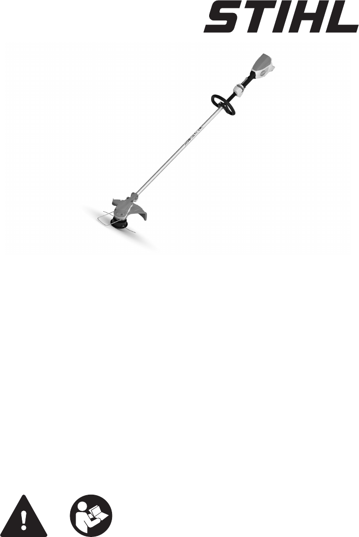
STIHL FSA 60 R 2 - 20 Instruction Manual
English 1 Introduction Dear Customer, Thank you for choosing STIHL. We develop and manufacture our quality products to meet our customers’ requirements. The products are designed for reliability even under extreme con‐ ditions. STIHL also stands for premium service quality. Our dealers guarantee competent advice and instruction as well as comprehensive service support. IMPORTANT! READ BEFORE USING AND KEEP IN A SAFE PLACE FOR REFERENCE. 2 2.
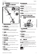
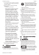
Overview Overview 3.1 12 Connecting cable The connecting cable connects the charger to the mains plug. Brushcutter, battery and charger 13 Charger The charger charges the battery. 1 2 # 5 3 6 10 # 11 13 4 14 Battery The battery supplies power to the brushcutter. 12 15 LEDs The LEDs indicate the state of charge of the battery and any faults. # 16 Button The button activates the LEDs on the battery. 14 15 7 3.
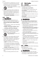
English 4 Safety Precautions 4 LEDs flash red. There is a malfunc‐ tion in the battery. 15m (50ft) Protect battery from heat and fire. LED glows green and LEDs on battery glow or flash green. Battery is being charged. Protect the battery from rain and mois‐ ture and do not immerse it in liquids. LED flashes red. No electrical contact between battery and charger or mal‐ function in battery or charger.
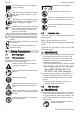
4 Safety Precautions English ► If you pass the trimmer, battery and charger on to another person: Always give them the instruction manual. ► Make sure the user meets the following requirements: – The user must be rested. – The user must be in good physical condition and mental health to operate and work with the trimmer, battery and charger. If the user’s physical, sensory or mental ability is restricted, he or she may work only under the supervision of or as instructed by a responsi‐ ble person.
English 4 Safety Precautions ■ The brushcutter is not waterproof. If you work in the rain or in a damp environment, an elec‐ tric shock may occur. The user may be injured and the brushcutter may be damaged. ► Do not work in the rain or in a damp environment. ■ Electrical components of the brushcutter can produce sparks. Sparks can cause fires and explosions in a flammable or explosive envi‐ ronment. This can result in serious injuries or death and damage to property.
4 Safety Precautions dered inoperative. This can result in serious injuries. ► Work only with an undamaged deflector. ► Work with a correctly installed line limiter blade. ► If you have any queries: Contact your STIHL servicing dealer. 4.6.3 Mowing Head The mowing head is in a safe condition if the fol‐ lowing points are observed: – The mowing head is not damaged. – The mowing head is not jammed. – The mowing lines are properly installed.
English ■ ■ ■ ■ ■ 4 Safety Precautions ► Keep the cutting attachment close to the ground. ► Watch out for obstacles. ► Stand on the ground while working and keep a good balance. ► If you begin to feel tired: Take a break. The rotating cutting attachment can cut the user. This can result in serious injuries. ► Do not touch the rotating cutting attachment. ► If the cutting attachment is blocked by an object: Switch off the trimmer and remove the battery. Then remove the object causing the blockage.
4 Safety Precautions ■ ■ ■ ■ ► Lay the connecting and extension cables on a dry surface. The extension cable becomes hot during oper‐ ation. If the heat cannot dissipate, it may cause a fire. ► If you use a cable drum: Unwind the exten‐ sion cable to its full length. If electric cables or pipes are embedded in the wall, they may be damaged when the charger is mounted on a wall. Contact with electric cables can result in an electric shock. This can result in serious injuries and damage to prop‐ erty.
English 5 Preparing Trimmer for Operation ► Store the battery in a confined space. ► Store the battery separately from the trimmer and charger. ► Store the battery in non-conductive packag‐ ing. ► Use and store the battery at temperatures between -10°C and +50°C. 4.11.3 Charger WARNING ■ Children are not aware of and cannot assess the dangers of a charger. Children may sus‐ tain serious or fatal injuries. ► Remove the battery. ► Store the charger out of the reach of chil‐ dren.
6 Charging the Battery, LEDs 3 Mounting the Charger on a Wall 2 The charger can be mounted on a wall. 2 1 a 3 4 1 b e a ► e 0000-GXX-0609-A0 d Check the following points when mounting the charger on a wall: – Suitable fixing materials. – The charger is level. The following dimensions are maintained: – a = at least 100 mm – b (for AL 101) = 75 mm – b (for AL 300 and AL 500) = 120 mm – c = 4.5 mm – d = 9 mm – e = 2.5 mm 6.
English LED on Charger 1 2 The LED indicates the operating status of the charger. If the LED glows green, the battery is being charged. ► If the LED flashes red: Rectify the malfunction. Malfunction in charger. 7 Assembling the Trimmer 7.1 Mounting the bump guard ► Switch off the brushcutter and remove the bat‐ tery. 2 2 1 0000097550_001 The bump guard (1) need not be removed. 7.2 4 5 6 7 ► Fit the clamp (4) in the loop handle (3). ► Place the loop handle (3) with clamp (4) on the shaft (5).
8 Adjusting Trimmer for User English Adjusting Trimmer for User 8.1 Adjusting and Setting the Loop Handle The loop handle can be set to different positions to suit the height and reach of the user. ► Switch off the brushcutter and remove the bat‐ tery. ► Position the mowing head (1) on the shaft (2). ► Hold the mowing head (1) with your hand. ► Manually rotate the upper part (3) clockwise and tighten it. a 2 Removing the Mowing Head ► Switch off the brushcutter and remove the bat‐ tery.
English 9.2 10 Switching the Trimmer On/Off Removing the Battery If the trigger (2) and the Ergo lever (3) are released, the trigger (2) is locked. To unlock the trigger (2), push and hold the release slide (1) again towards the loop handle. ► Stand the trimmer on a level surface. ► Hold one hand in front of the battery compart‐ ment to ensure the battery does not fall out. 10.2 0000-GXX-1492-A0 2 1 ► Press the locking lever (1) with your other hand. The battery (2) is unlocked and can be removed.
12 Operating the Trimmer Testing the Battery matically cuts the mowing lines to the correct length. ► Press button on battery. The LEDs glow or flash. ► If the LEDs do not glow or flash: Do not use the battery and contact your STIHL servicing dealer. There is a malfunction in the battery. 12 Holding and Controlling the Brushcutter 2 0000097273_001 12.1 Operating the Trimmer ► Hold the brushcutter firmly with one hand on the control handle – wrap your thumb around the handle.
English 15 Storing The battery is subject to the requirements for the transport of dangerous goods. The battery is classified as UN 3480 (lithium-ion batteries) and has been tested in accordance with UN Manual of Tests and Criteria, Part III, sub-section 38.3. For transport regulations see www.stihl.com/ safety-data-sheets 14.3 Transporting the Charger ► Disconnect the plug from the wall outlet. ► Remove the battery. ► Wind up the connecting cable and attach it to the charger.
Maintenance 17 17.1 English Maintenance Maintenance Intervals The maintenance intervals are dependent on the environmental and operating conditions. STIHL recommends the following maintenance inter‐ vals: Every 12 months ► Have the trimmer checked by a STIHL servic‐ ing dealer. 18 18.1 attachment and contact your STIHL servicing dealer. ► If the battery has a malfunction or is damaged: Replace the battery. ► If the charger has a malfunction or is dam‐ aged: Replace the charger.
English 20 Specifications Condition Mowing head cannot be unscrewed by hand. Charge process does not start when battery is inserted in the charger. 19.2 LEDs on Bat‐ tery 1 LED glows red. LED on Charger Battery not being LED flashes charged. red. 20.1 Remedy Normal battery life has been exceeded. Mowing head over‐ tightened. ► Replace the battery. Battery too hot or too cold. Remedy No electrical contact between charger and battery. Malfunction in charger.
21 Combinations of Cutting Attachments and Deflectors tools. The vibration levels actually occurring may vary from the values indicated, depending on the type of application. The vibration levels indicated can be used for an initial estimate of the vibration stress. The actual vibration stress has to be esti‐ mated. The times when the power tool is switched off and the times when it is switched on but running under no load can be taken into account in the estimate.
English 24 EC Declaration of Conformity ANDREAS STIHL AG & Co. KG pp Dr. Jürgen Hoffmann, Head of Product Data, Regulations and Licensing 24.2 STIHL AL 101 Charger Con‐ formity Notice This charger has been manufactured and put on the market in accordance with the following directives: 2014/35/EU, 2014/30/EU and 2011/65/EU. The year of manufacture, country of manufacture and serial number are applied to the blower. The complete EC Declaration of Conformity is available from ANDREAS STIHL AG & Co.
24 EC Declaration of Conformity 0458-832-0121-B. VA0.B21.
English 22 24 EC Declaration of Conformity 0458-832-0121-B. VA0.B21.
24 EC Declaration of Conformity 0458-832-0121-B. VA0.B21.
0458-832-0121-B *04588320121B* www.stihl.