STIHL MS 171, 181, 211 2 - 44 Instruction Manual
English 7 8 9 30 31 32 33 34 35 36 37 Thank you for choosing a quality engineered STIHL product. It has been built using modern production techni‐ ques and comprehensive quality assurance. Every effort has been made to ensure your satis‐ faction and trouble-free use of the product. Dr. Nikolas Stihl 1 Guide to Using this Manual This Instruction Manual refers to a STIHL chain saw, also called a machine in this Instruction Manual. 1.
2 Safety Precautions 1.2 Symbols in text WARNING Warning where there is a risk of an accident or personal injury or serious damage to property. NOTICE Caution where there is a risk of damaging the machine or its individual components. 1.3 Engineering improvements STIHL's philosophy is to continually improve all of its products. For this reason we may modify the design, engineering and appearance of our products periodically.
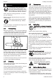
English 2 Safety Precautions 2.6 WARNING To reduce the risk of eye injuries, wear tight-fitting safety goggles con‐ forming to standard EN 166 or a face shield. Make sure that the safety gog‐ gles and the face shield fit correctly. Wear "personal" hearing protection – for exam‐ ple, ear defenders. Wear a hard hat wherever there is any risk of falling objects. Wear sturdy protective gloves made of a resistant material (e.g. leather).
– – – – – – – – – cap, hose connections and the manual fuel pump (on machines so equipped). If there are any leaks or damage, do not start the engine – risk of fire. Have your saw repaired by a serv‐ icing dealer before using it again. Check operation of chain brake, front hand guard Correctly mounted guide bar Correctly tensioned chain The trigger and trigger lockout must move freely and spring back to the idle position when they are released.
English Examine the saw chain periodically at short inter‐ vals and as soon as you note any tangible changes: – Switch off the engine; wait until the saw chain is stationary – Check condition and secure fitting – Check sharpness Never touch the saw chain when the engine is running.
3 Reactive Forces The machine must be serviced regularly. Do not attempt any maintenance or repair work not described in the Instruction Manual. All other work should be carried out by a servicing dealer. STIHL recommends that maintenance and repair work be carried out only by authorised STIHL dealers. STIHL dealers receive regular training and are supplied with technical information. Use only high-quality spare parts. Otherwise, there may be a risk of accidents and damage to the machine.
English 4 Working Techniques object, e.g. when another limb is touched acci‐ dentally during limbing. – when the chain at the nose of the guide bar is pinched in the cut. 3.3 Quickstop chain brake: the chain pulls the saw forward – to reduce this risk, always engage the spiked bumper securely in the tree or limb. 3.6 Pushback (B) 3.4 To reduce the risk of kickback – Work cautiously and avoid situations which could cause kickback. – Hold the saw firmly with both hands and main‐ tain a secure grip.
English 4 Working Techniques chain saw in the vicinity of easily combustible materials, dry plants or scrub. It is mandatory that you ask the responsible forestry office about the current fire hazard. Country-specific legislation on felling technique must be complied with during felling work. 4.1 Sawing Do not operate your saw with the starting throttle lock engaged. Engine speed cannot be control‐ led with the throttle trigger in this position.
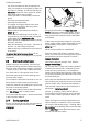
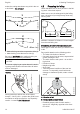
English 4 Working Techniques erwise the cutting attachment may stick in the cut or kick back – risk of injury! Preparing for felling Make sure no-one is endangered by the falling tree – the noise of your engine may drown any warning calls. 1 ► Make relieving cut at the compression side (1) ► Make bucking cut at the tension side (2) Be wary of pushback when making bucking cut from the bottom upwards (underbuck).
4 Working Techniques English 001BA146 KN Preparing work area at base of tree – First clear the tree base and work area from interfering limbs and brush to provide a secure footing. – Carefully clear the base of the trunk (e.g., with an axe) – sand, stones and other foreign objects will blunt the saw chain – Remove largest buttresses: first the largest buttress – saw first vertically, then horizontally – only if the tree is in sound condition 4.
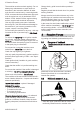
English 4.4 4 Working Techniques Sapwood cuts – With rotten trunks, leave a wider strip Sapwood cuts in long-fibered softwood help pre‐ vent sapwood splintering when the tree falls. Make cuts at both sides of the trunk at same height as bottom of felling notch to a depth of about 1/10 of trunk diameter. On large diameter trees, cut to no more than width of guide bar. Do not make sapwood cuts if wood is diseased. Basic information on felling cut C C 1/10 Ø E G 3. 2.
4 Working Techniques English Select suitable felling wedges dependent on the trunk diameter and the width of the kerf (ana‐ logue to felling cut (E)). Contact the STIHL dealer for the selection of the felling wedge (suitable length, width and height). 4.6 Selecting the appropriate felling cut The selection of the appropriate felling cut is dependent on the same tree characteristics that must be noted when determining the direction of fall and the escape paths.
English 4 Working Techniques – Do not cut into the stabilizing strap – Cut horizontally – Do not cut into the holding strap. The felling cut must be continued on the oppo‐ site side of the trunk. 001BA266 KN Ensure that the second cut is at the same level as the first cut.
5 Cutting Attachment English Shout a second warning immediately before the tree falls. ► With outstretched arms, cut through the hold‐ ing strap at a downward angle from outside. Cutting Attachment Your saw comes standard with a chain scabbard that matches the cutting attachment. If guide bars of different lengths are mounted to the saw, always use a chain scabbard of the cor‐ rect length which covers the complete guide bar.
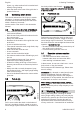
English 7 Mounting the Bar and Chain (quick chain tensioner) ► Turn the screw (1) counterclockwise until the tensioner slide (2) butts against the left end of the housing slot. 6.2 Disengage the chain brake. ► Turn the tensioning screw (4) clockwise until there is very little chain sag on the underside of the bar – and the drive link tangs are engaged in the bar groove. ► Refit the sprocket cover and screw on the nut only fingertight. ► Go to chapter on "Tensioning the Saw Chain" 001BA186 KN 7 7.
7 Mounting the Bar and Chain (quick chain tensioner) 7.4 ► Remove screw (2) English Fitting the saw chain 3 2310BA016 KN 1 ► Position tensioning gear (1) and guide bar (3) relative to one another 1 2310BA017 KN ► Insert and tighten screw (2) WARNING Releasing the chain brake Put on protective gloves – risk of injury by the sharp cutters. 001BA186 KN 7.
English 8 Tensioning the Saw Chain (side chain tensioner) Tensioning the Saw Chain (side chain tensioner) 142BA063 KN 8 135BA011 KN 1 ► Guide the drive link into the bar groove (see arrow) and turn the tensioning gear to the left as far as possible ► Fit chain sprocket cover, sliding the guide lugs into the engine housing openings Retensioning during cutting work: ► Switch off the engine. ► Loosen the nut. ► Hold the bar nose up.
10 Checking Chain Tension English 11.2 ► Check chain tension frequently – see chapter on "Operating Instructions". 10 NOTICE Checking Chain Tension Unsuitable fuels or lubricants or mix ratios other than those specified may result in serious dam‐ age to the engine. Poor quality gasoline or engine oil may damage the engine, sealing rings, hoses and the fuel tank. 142BA064 KN 11.2.1 ► Shut off the engine. ► Wear work gloves to protect your hands.
English 12 Fueling Fuel mix ages – only mix sufficient fuel for a few weeks work. Do not store fuel mix for longer than 30 days. Exposure to light, the sun, low or high temperatures can quickly make the fuel mix unusable. 001BA240 KN STIHL MotoMix may be stored for up to 2 years without any problems. ► Thoroughly shake the mixture in the canister before fueling your machine. WARNING left: right: Pressure may build up in the canister – open it carefully.
12 Fueling English 12.3.4 ► Remove the filler cap 12.3.2 Checking the lock Filling with fuel Take care not to spill fuel while fueling and do not overfill the tank. 12.3.3 001BA223 KN STIHL recommends using the STIHL filling sys‐ tem for fuel (special accessory).
12 Fueling 001BA226 KN 001BA234 KN English ► Fit filler cap and turn it counterclockwise until it engages in the seat of the filling port ► Continue to turn the filler cap counterclockwise (approx. 1/4 turn) – this will twist the base of the cap into the correct position ► Turn the filler cap clockwise and close it – see the section "Closing" and "Checking the lock" 12.4.1 Filler cap with marking 001BA237 KN 12.
13 Chain Lubricant English 12.4.4 If the filler cap will not lock onto the fuel tank ► Hold the filler cap down and turn it clockwise until it engages 1 001BA231 KN left: right: 001BA238 KN 001BA233 KN The base of the filler cap is twisted in relation to the upper part.
English 14 Filling Chain Oil Tank NOTICE Biological chain oil must be resistant to aging (e.g. STIHL BioPlus), since it will otherwise quickly turn to resin. This results in hard deposits that are difficult to remove, especially in the area of the chain drive and chain. It may even cause the oil pump to seize. The service life of the chain and guide bar depends on the quality of the lubricant. It is therefore essential to use only a specially formu‐ lated chain lubricant.
17 Winter Operation 16.3 Saw chain, lock 143BA011 KN 16.1 English – in an emergency – when starting – when idling Press the hand guard towards the nose of the guide bar with the left hand - or automatically due to kickback: Saw chain is blocked - and stops running. 16.2 Checking Operation of the Chain Brake Before starting work: Run engine at idle speed, engage the chain brake (push hand guard towards bar nose) and open the throttle wide for (no more than 3 seconds) – the chain must not rotate.
English 18 Starting / Stopping the Engine 18 1 winter operation 2 summer operation ► Fit the shroud – see "Shroud" Heated air is now drawn in from around the cylin‐ der and circulates around the carburetor – this helps prevent carburetor icing. 18.1 Starting / Stopping the Engine Positions of the master control lever NOTICE At temperatures above + 20 °C, always return the slide to the position for summer operation! Risk of engine malfunction – overheating! 17.
18 Starting / Stopping the Engine Simultaneously pressing the throttle trigger lock‐ out and blipping the throttle trigger causes the master control lever to jump from the warm start n position to the operating position F. English 18.4.1 On the ground To switch off the engine, set the master control lever to Stop 0. 18.2.2 Position starting acceleration n – if engine is warm (once the engine has been running for approx.
English 18.4.
18 Starting / Stopping the Engine 18.6.1 English ► Simultaneously press the throttle trigger lock‐ out (2) and throttle trigger – set the master control lever (3): Versions with fuel pump Position choke shutter closed l – if engine is cold (even if the engine has stalled during opening of throttle after starting) Position starting acceleration n – if engine is warm (once the engine has been running for approx. one minute) ► Hold and start the chain saw 18.
English 19 Operating Instructions ► Set the master control lever to starting accel‐ eration n – even if the engine is cold ► Restart the engine 19 19.1 Operating Instructions During the break-in period A factory new machine should not be run at high revs (full throttle off load) for the first three tank fillings. This avoids unnecessarily high loads dur‐ ing the break-in period.
20 Taking Care of the Guide Bar English NOTICE The chain contracts as it cools down. If it is not slackened off, it can damage the crankshaft and bearings. 19.2.4 After a long period of full-throttle oper‐ ation After a long period of full-throttle operation, allow engine to run for a while at idle speed so that the heat in the engine can be dissipated by flow of cooling air. This protects engine-mounted com‐ ponents (ignition, carburetor) from thermal over‐ load. 19.
23 Cleaning the Air Filter 533BA009 KN English ► Push the two locking tabs upwards, tilt the air filter towards the rear handle and remove. NOTICE 533BA008 KN To avoid damaging the filter, do not use tools for removing and installing the air filter. ► Blow out the filter with compressed air from the clean air side. Top illustration. If the filter fabric is caked with dirt or no com‐ pressed air is available: ► Wash the filter in a clean, non-flammable solu‐ tion (e.g. warm soapy water) and then dry.
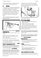
25 Spark Arresting Screen in Muffler 24.3 English Standard Setting It is usually necessary to change the setting of the idle speed screw (LA) after every correction to the low speed screw (L). 24.5 533BA020 KN H L ► Turn high speed screw (H) counterclockwise as far as stop (no more than 3/4 turn). ► Turn the low speed screw (L) clockwise as far as stop, then turn it back 1/4 turn. 24.
English 26 26 Spark Plug Spark Plug ► If the engine is down on power, difficult to start or runs poorly at idle speed, first check the spark plug. ► Fit a new spark plug after about 100 operating hours – or sooner if the electrodes are badly eroded. Install only suppressed spark plugs of the type approved by STIHL – see "Specifica‐ tions". 000BA045 KN 26.1 1 Removing the spark plug ► Remove the shroud – see "Shroud".
29 Checking and Replacing the Chain Sprocket English ► Store the machine in a dry, high or locked location, out of the reach of children and other unauthorized persons. 29 5 Checking and Replacing the Chain Sprocket 6 ► Remove chain sprocket cover, saw chain and guide bar. ► Release chain brake – pull hand guard against the front handle 29.1 2 1 Fit new chain sprocket 4 3 1 001BA121 KN – after use of two saw chains or earlier – if the wear marks (arrows) are deeper than 0.
English 30.1 Maintaining and Sharpen‐ ing the Saw Chain The diameter of file to be used depends on the chain pitch – see table "Sharpening tools". Sawing effortlessly with a prop‐ erly sharpened saw chain A properly sharpened saw chain cuts through wood effortlessly even with very little pushing. Never use a dull or damaged saw chain – this leads to increased physical strain, increased vibration load, unsatisfactory cutting results and increased wear.
30 Maintaining and Sharpening the Saw Chain File holder 689BA025 KN 90° 689BA018 KN 30.4 English ► Use a file holder Always use a file holder (special accessory, see table "Sharpening tools") when sharpening saw chains by hand. File holders have markings for the sharpening angle. To check the angles 001BA203 KN 30.
English 30.7 30 Maintaining and Sharpening the Saw Chain Depth gauge setting mark) is lowered at the same time as the depth gauge of the cutter. WARNING a 689BA023 KN The rest of the humped drive link must not be filed; otherwise, this could increase the tendency of the chain saw to kick back. 689BA051 KN The depth gauge determines the depth to which the cutter penetrates the wood and thus the chip thickness.
31 Maintenance and Care English ► Lay the file gauge on the saw chain – the high‐ est point of the depth gauge must be flush with the file gauge ► After sharpening, clean the saw chain thor‐ oughly, removing any filings or grinding dust – lubricate the saw chain thoroughly ► In the event of extended periods of disuse, store saw chains in cleaned and oiled condi‐ tion Sharpening tools (special accessories) Chain pitch Round file Round file File holder File gauge Taper square Sharpening file ^ set1) Inches
Chain catcher check As required If faulty Annually Monthly Weekly X X If damaged Fuel pick-up body / filter in fuel check tank Clean, replace filter insert replace Fuel tank Clean Lubricating oil tank Clean Chain lubrication check Saw chain Check, pay attention to sharpness Checking the chain tension sharpen Guide bar Check (wear, damage) Clean and turn over Deburr replace Chain sprocket check Air filter Clean replace Anti-vibration elements check Have replaced by servicing dealer1) Air intake on f
As required If damaged If faulty Annually Monthly Weekly replace replace Safety information label 32 Whenever tank is refilled The following maintenance intervals apply for normal operat‐ ing conditions only. When working under difficult conditions (high accumulation of dust, highly resinous lumber, lumber from tropical trees, etc.) or longer than normal each day, the specified intervals must be shortened accordingly. If you only use the tool occasionally, extend the intervals accordingly.
English 33 Specifications Engine power to ISO 7293: 1.3 kW (1.8 bhp) at 10,000 rpm 2,800 rpm Idle speed:1) 33.1.2 MS 181, MS 181 C Displacement: Bore: Stroke: Engine power to ISO 7293: Idle speed:1) 33.1.3 MS 211, MS 260 C Displacement: Bore: Stroke: Engine power to ISO 7293: Idle speed:1) 33.2 31.8 cc 38 mm 28 mm 1.5 kW (2.0 bhp) at 10,000 rpm 2,800 rpm 35.2 cc 40 mm 28 mm 1.7 kW (2.
34 Ordering Spare Parts MS 171 C: MS 181: MS 181 C: MS 211: MS 211 C: 33.8.3 English 112 dB(A) 112 dB(A) 112 dB(A) 113 dB(A) 113 dB(A) Vibration measurement ahv,eq to ISO 22867 MS 171: MS 171 C: MS 181: MS 181 C: MS 211: MS 211 C: Handle, left Handle, right 4.0 m/s2 4.5 m/s2 3.5 m/s2 3.5 m/s2 3.5 m/s2 3.0 m/s2 3.5 m/s2 3.0 m/s2 3.5 m/s2 3.5 m/s2 3.5 m/s2 3.5 m/s2 The K‑factor in accordance with Directive 2006/42/EC is 2.
English 37 EC Declaration of Conformity packaging to an approved disposal site for envi‐ ronment-friendly recycling. Contact your STIHL servicing dealer for the lat‐ est information on waste disposal. 37 EC Declaration of Con‐ formity ANDREAS STIHL AG & Co. KG Badstr. 115 D-71336 Waiblingen Deutsche Prüf- und Zertifizierungsstelle für Landund Forsttechnik (NB 0363) Spremberger Straße 1 D-64823 Groß-Umstadt Certification No.
37 EC Declaration of Conformity 0458-533-8321-E English 45
English 46 37 EC Declaration of Conformity 0458-533-8321-E
37 EC Declaration of Conformity 0458-533-8321-E English 47
0458-533-8321-E *04585338321E* www.stihl.