STIH) STIHL MS 171, 181, 211 2012-10
Contents 1. 2. 3. 3.1 3.2 3.3 3.4 3.5 Introduction Safety Precautions Specifications Engine Fuel System Ignition System Chain Lubrication Tightening Torques 3 8. Engine 8.1 8.8 8.8.1 Muffler / Spark Arresting Screen Leakage Test Preparations Vacuum Test Pressure Test Oil Seals Removing and Installing the Shroud Removing and Installing the Engine Crankshaft Ball Bearings/ Crankshaft Piston Piston Rings 9. Ignition System 40 9.1 9.1.
Contents 14. Fuel System 72 14.1 14.2 14.
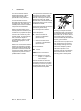
Introduction This service manual contains detailed descriptions of all the typical repair and servicing procedures for this power tool. You should make use of the illustrated parts lists while carrying out repair work. They show the installed positions of the individual components and assemblies. Refer to the latest edition of the relevant parts list to check the part numbers of any replacement parts. A fault on the machine may have several causes.
33RA000 TG 2. After disengaging the chain brake and removing the chain sprocket cover, bar and chain, the powerhead’s bar stud is pushed through the outer hole in the mounting plate and secured with the nut (arrow). The machine is held in position on the mounting plate by the two screw heads on the engine housing. Always use original STIHL replacement parts. They can be identified by the STIHL part number, the STIH) logo and the STIHL parts symbol ( This symbol may appear alone on small parts.
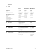
3. Specifications 3.1 Engine Displacement: Bore: Stroke: Engine power to ISO 7293: Max. permissible engine speed with bar and chain: Idle speed: Clutch: Clutch engages at: Crankcase leakage test at gauge pressure: under vacuum: MS 171 MS 181, MS 181 C MS 211, MS 211 C 30.1 cm3 37 mm 28 mm 1.3 kW (1.8 PS) at 9,500 rpm 31.8 cm3 38 mm 28 mm 1.5 kW (2.0 PS) at 9,500 rpm 35.2 cm3 40 mm 28 mm 1.7 kW (2.
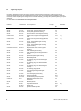
3.5 Tightening Torques DG and P (Plastoform) screws are used in polymer and light metal components. These screws form a permanent thread when they are installed for the first time. They can be removed and installed as often as necessary without impairing the strength of the screwed assembly, providing the specified tightening torque is observed. For this reason it is essential to use a torque wrench. Fastener Thread size For component Torque Remarks Nm Screw Screw Screw Collar screw P 4x12 B 3.
Remarks: 1) Loctite 243 medium strength 2) Degrease crankshaft/flywheel faces and mount oil-free Use the following procedure when refitting a DG or P screw in an existing thread: Place the screw in the hole and rotate it counterclockwise until it drops down slightly. Tighten the screw clockwise to the specified torque. This procedure ensures that the screw engages properly in the existing thread and does not form a new thread and weaken the assembly.
4. Troubleshooting 4.
4.
4.3 Chain Lubrication In the event of trouble with the chain lubrication system, check and rectify other sources of faults before disassembling the oil pump. .
4.4 Rewind Starter Condition Cause Remedy Starter rope broken Rope pulled out too vigorously as far as stop or over edge, i.e.
4.5 Ignition System Exercise extreme caution while carrying out maintenance and repair work on the ignition system. The high voltages which occur can cause serious or fatal accidents!.
Condition Cause Remedy No spark Spark plug faulty Install new spark plug Faulty insulation or short in short circuit wire Check short circuit wire for short circuit to ground Break in ignition lead or insulation damaged Check ignition lead, replace ignition module if necessary Ignition module faulty Install new ignition module MS 171, MS 181, MS 211 13
4.6 Carburetor Condition Cause Remedy Carburetor floods; engine stalls Inlet needle not sealing.
Condition Cause Remedy Engine will not idle, idle speed too high Throttle shutter opened too wide by idle speed screw (LA) Reset idle speed screw (LA) correctly Oil seals/engine leaking Seal or replace oil seals/ engine Air valve contaminated – does not close Clean air valve, replace if necessary Air valve stiff Check air valve, replace if necessary Throttle rod stiff – throttle shutter does not close Replace throttle rod and lever Idle jet bores or ports blocked Clean the carburetor Idle je
Condition Cause Remedy Engine speed drops quickly under load – low power Air filter dirty Clean the air filter Throttle shutter not opened fully Check throttle rod Tank vent faulty Replace tank vent Fuel pickup body dirty Install new pickup body Fuel strainer dirty Clean fuel strainer in carburetor, replace if necessary Leak in fuel line between tank and fuel pump Install new fuel line Setting of high speed screw (H) too rich Check basic carburetor setting, correct if necessary Main jet bo
4.
5. Cutting Attachment When installing the adjusting wheel, check that its teeth face the cover plate. 3 1 165RA006 TG 533RA001 TG 2 1 – Reassemble in the reverse sequence. Wear gloves to protect your hands from injury. : Apply screwdriver to side (1) of wing nut and pry it out of its seat. : Unscrew the hex nut (1). – Check the wing nut and replace if necessary. : Remove the chain sprocket cover (2). 5.
6. Clutch – Troubleshooting, b 4.1 1 1 – Remove the chain sprocket cover, bar and chain, b 5 1 533RA007 TG : Push the locking strip (1) 0000 893 5904 into the spark plug hole until it butts against the cylinder wall (arrow) as shown. 533RA012 TG 533RA009 TG – Remove the clutch drum, b 6.1 – Pull the clutch shoes off the carrier. : Pull the retainers (1) off the clutch shoes. – Remove the shroud, b 8.4 TOP 533RA013 TG : Pull off the spark plug boot (1).
2 1 TOP : Fit the clutch shoes (1) over the arms (2). : Check the clutch – all springs (arrows) must be properly attached. 533RA021 TG 533RA018 TG 533RA015 TG 1 : Use the hexagon (arrow) to screw the clutch (1) onto the crankshaft stub. Check the position of the locking strip and then tighten down the clutch firmly – left-hand thread. – Tightening torques, b 3.5 – Remove the locking strip from the cylinder. : Clamp the clutch in a vise (arrow).
Clutch Drum 1 1 TOP TOP 533RA024 TG 533RA022 TG 1 : Pull off the needle cage (1). 2 533RA025 TG 6.1 The notch (arrow) in the clutch drum must engage the worm’s spring (1). – On machines with ErgoStart, relieve spring tension, b 10.4 – Clean the needle cage and crankshaft stub, b 16 Use the mark (2) for alignment.
The chain brake is one of the most important safety devices on the chainsaw. Its efficiency is measured in terms of the chain braking time, i.e. the time that elapses between activating the brake and the saw chain coming to a complete standstill. Contamination (with chain oil, chips, fine particles of abrasion, etc.) and smoothing of the friction surfaces of the brake band and clutch drum impair the coefficient of friction. This, in turn, reduces the frictional forces and thus prolongs the braking time.
Install a new brake band if there are noticeable signs of wear (large areas on inside diameter and/or parts of outside diameter) and its remaining thickness is less than 0.6 mm. 1 : Push the brake band (1) into its guides (arrows). 533RA033 TG 2 533RA059 TG 533RA030 TG 1 If the pegs have broken off, the cover can be serviced. – Drill out the recesses exactly in the center (arrow): a (1) = o 4.5 mm b (2) = o 5.5 mm 533RA031 TG 1 TOP 1 – Place the cover (1) in position.
7.3 Brake Lever 2 2 – Troubleshooting, b 4.2 : Remove the E-clip (arrow). 533RA040 TG 533RA037 TG 1 533RA035 TG 1 : Pull the brake lever (2) out of the hand guard (1). – Remove the brake band, b 7.2 – Inspect the brake lever and hand guard and replace if necessary. 1 – Push the hand guard away from the front hand to relax the brake spring. 1 : Lift and turn the strap (1) a little, then push it to the left as far as the hole (arrow) and remove it.
– Locate the hand guard at the starter side and fit the screw. 533RA047 TG 2 533RA042 TG 1 1 : Push the hand guard and brake lever over the machine until they butt against the pivot pins. 533RA045 TG – Lubricate the pivot pins, b 16 : Attach brake spring (1) to the brake lever (arrow). – Push on the spacer sleeve. 1 – Fit the strap (1). 2 533RA043 TG 533RA048 TG : Fit the E-clip (2).
Flat Spring 7.5 Pins 2 The flat spring and hand guard cam hold the hand guard in position. The anchor pins secure the springs. Worn pins must be replaced. – Remove the brake lever, b 7.3 All parts have been removed from the pins in the following illustrations for greater clarity. 1 3 533RA053 TG 7.4 1 3 2 1 b 533RA051 TG 1 – Remove the engine, b 8.5 : Use a suitable punch to drive out the pins (1+2) in the direction of the engine – use suitable support.
7.6 Chain Tensioner 7.7 2 1 For machines with quick chain tensioner see b 5 Bar Mounting Studs 3 2 – Troubleshooting, b 4.2 : Remove the spur gear (1) and tensioner slide (2). 2 1 533RA003 TG 533RA057 TG – Remove the chain sprocket cover, bar and chain, b 5 – Remove the chain sprocket cover, bar and chain, b 5 4 : Push stud puller 5910 893 0501 (1) over the collar stud (2) as far as it will go. Unscrew the stud.
Engine 8.1 Muffler / Spark Arresting Screen 1 1 533RA062 TG Always check and, if necessary, repair the fuel system, carburetor, air filter and ignition system before looking for faults on the engine. – Troubleshooting, b 4 : Remove the heat shield (1). : Place the heat shield (1) in position and use the recesses (arrows) to line it up on the sealing face of the exhaust port. 1 1 533RA063 TG : Pry the plugs out of the muffler by means of the tabs (arrows).
Leakage Test The sealing plate must completely fill the space between the two screws. Defective oil seals and gaskets or cracks in castings are the usual causes of leaks. Such faults allow supplementary air to enter the engine and upset the fuel-air mixture. This makes adjustment of the prescribed idle speed difficult, if not impossible. Moreover, the transition from idle speed to part or full throttle is not smooth. 533RA060 TG – Remove the carburetor, b 14.
Vacuum Test Oil seals tend to fail when subjected to a vacuum, i.e. the sealing lip lifts away from the crankshaft during the piston's induction stroke because there is no internal counterpressure. A test can be carried out with pump 0000 850 1300 to detect this kind of fault. 1 If the vacuum reading remains constant, or rises to no more than 0.3 bar within 20 seconds, it can be assumed that the oil seals are in good condition.
1 217RA085 TG 2 – Clamp the puller arms. Clutch side – Pull out the oil seal. – Remove the chain sprocket cover, bar and chain, b 5 Take care not to damage the crankshaft stub. – Remove the clutch, b 6 – Cleaning the sealing face, b 16 – Remove the oil pump, b 13.3 – Lubricate sealing lips of new oil seal with grease, b 16 Use oil seal (1) 9638 003 1581 if the engine is not opened. Install oil seal (2) 9639 003 1585 if the engine has been opened up.
– Slip the oil seal, closed side facing the engine, over the installing sleeve. 1 – Remove the installing sleeve (1). 1 2 : Apply puller (1) 5910 890 4400 with No. 3.1 jaws 0000 893 3706. – Clamp the puller arms. : Push the worm (1) onto the crankshaft stub as far as stop – it must engage the oil pump pinion. 533RA081 TG – Free off the oil seal in its seat by tapping it with a suitable tube or a punch. : Use press sleeve (1) 1123 893 2400 to install the oil seal (2). – Pull out the oil seal.
: Apply screwdriver above the spindle (arrow) and push it into the slide (1). : Push the shroud (1) down as far as stop and secure in position with the slide lock (2). 1 533RA074 TG 533RA084 TG 1 2 533RA085 TG 1 : Remove the worm (1). – Remove the slide (1). 8.5 533RA091 TG – Inspect the slide and spindle and replace if necessary. Removing and Installing the Engine 1 533RA086 TG 1 : Push the bearing lugs of shroud (1) into the guides (arrows) until they snap into position.
– Apply fresh sealant to sealing faces, b 16 533RA097 TG 533RA091 TG 533RA093 TG – Clean the sealing faces on the cylinder, engine pan and oil seals, remove gasket residue if necessary, b 16 – Position the engine in the engine housing and hold it there – the holes in the engine housing, engine pan and cylinder must line up. : Lift the crankshaft out of the bearing seats (arrows). : Fit and tighten down the cylinder mounting screws (arrows).
– Inspect the cylinder and clean the sealing faces (arrows), remove gasket residue if necessary, b 16 1 Use oil seal (1) 9638 003 1581 if the engine is not opened. Install oil seal (2) 9639 003 1585 if the engine has been opened up. The sealing faces must be clean and show no signs of damage. Parts with damaged sealing faces must be replaced. 533RA104 TG 217RA085 TG 533RA102 TG 2 – Lubricate the piston, piston rings and cylinder wall with oil.
– Clean the crankshaft stub, b 16 – Install the engine, b 8.5 The pistons rings are compressed by the inner taper of the cylinder. : Carefully push the piston with crankshaft into the cylinder (arrow). 533RA110 TG 533RA106 TG – Reassemble all other parts in the reverse sequence. – Inspect and clean the mating face on the engine pan, remove gasket residue if necessary, b 16 The mating faces must be perfectly clean and not be damaged in any way. Replace parts with damaged mating faces. 8.
3 1 2 2 1 533RA115 TG 533RA119 TG 533RA121 TG 1 : The crankshaft (1), connecting rod (2) and needle bearing (3) are an inseparable unit. This means the crankshaft must always be replaced as a complete unit. Use a firm support (2) to protect the crankshaft. : Position the small diameter of assembly drift (1) 1110 893 4700 against the piston pin. When fitting a replacement crankshaft, always install new ball bearings and oil seals.
– Lubricate needle cage with oil. 533RA130 TG 1 533RA127 TG 533RA124 TG 1 : Remove the sleeve (1) from the installing tool 5910 890 2210. : Line up the piston as shown in the illustration so that the mark (arrow) points to the rear and the long crankshaft stub (1) is on the right. : Press the installing tool downwards into the sleeve until the magnet butts against the end of the guide slot. Use a suitable base (wooden board).
533RA136 TG 533RA134 TG 533RA132 TG – Install the snap rings at both sides. – Check the piston rings and replace if necessary., b 8.8.1 : Apply the installing tool 5910 890 2210 with the sleeve’s taper against the piston boss, hold the piston steady, center the tool shank exactly and press home until the snap ring slips into the groove. – Check the oil seals and ball bearings and replace if necessary., b 8.7 : Install the new piston rings in the grooves so that the radii face upward (arrows).
Ignition System Exercise extreme caution when troubleshooting and carrying out maintenance or repair work on the ignition system. The high voltages which occur can cause serious or even fatal accidents. Troubleshooting on the ignition system should always begin at the spark plug, b 4.5 – Remove the fan housing, b 10.1 and b 10.2 – the high voltage output with ignition lead (1) 1 – the connector tag (2) for the short circuit wire Testing in the workshop is limited to a spark test.
1 2 2 2 The ignition module (1) and ignition lead (2) are an assembly. – Fit the insulator (1) so that the stop (2) is against the upper hole. – Check the ignition module (1) and ignition lead and replace the ignition module if necessary. : Secure the insulator (1) with the lugs (arrows) on the bosses. 533RA118 TG 533RA143 TG 1 533RA146 TG 1 : Fit the ground wire (2) in the retainer (1) – ground wire must face the cylinder (arrow).
: Slide the setting gauge (1) 4118 890 6400 between the arms of the ignition module and the flywheel magnet. – Press the ignition module against the setting gauge. – Hold the ground wire terminal and tighten down the screws firmly. – Tightening torques, b 3.5 : Push the ignition lead (1) into the retainer (arrow) and pull it a little in the direction of the air filter. – Check operation – rotate the flywheel and make sure it does not touch the ignition module.
High voltage – risk of electric shock. – Crank the engine quickly with the rewind starter and check spark in the tester’s window (3). Using ZAT 3 ignition tester 5910 850 4520 – Before starting the test, install a new spark plug in the cylinder and tighten it down firmly The engine may start and accelerate during the test. If a spark is visible, the ignition system is in order. If no spark is visible in the window (3), check the ignition system with the aid of the troubleshooting chart, b 9.7 9.
: Make sure the leg spring (arrow) locates properly inside the spark plug boot. 533RA157 TG 533RA155 TG Inspect flywheel (1) and magnet poles (2) for cracks or other damage. If it is damaged or has turned blue, install a new flywheel. : Unscrew the flywheel nut (arrow). The flywheel bore and crankshaft stub must be free from grease, b 16. – On machines with ErgoStart, check the pawls and replace if necessary, b 10.4 If the flywheel is stuck, use the puller.
9.6 Short Circuit Wire 9.6.1 Testing 9.6.2 1 Removing and Installing : Disconnect short circuit wire (1). The short circuit and ground wires are combined in a wiring harness. If damaged, the complete wiring harness must be replaced. – Pull the short circuit and ground wires out of the retainer (arrow). When cleaning the machine, take care not to disconnect wires. 1 If the spark plug, ignition lead and spark plug boot are in order, check the short circuit wire. – Remove the fan housing, b 10.
1 2 : Check the short circuit wire (1) and ground wire (2) and replace wiring harness if necessary. : Fit the wiring harness (1) along the housing and push it, ground wire first, completely into the guide (arrow). A faulty ground wire can impair or prevent operation of the short circuit wire. For this reason also check the ground wire for contact and continuity. 533RA171 TG 1 533RA168 TG 533RA166 TG 1 1 : Press the wires into the guides (1) first, then into the guides (arrows).
9.6.3 Ground Wire 1 The short circuit and ground wires are combined in a wiring harness. If damaged, the complete wiring harness must be replaced. : Check operation – the short circuit wire’s connector must touch the contact spring (arrow) in position “0“. – Check for contact and continuity and replace wiring harness if necessary, b 9.6.1 – Install the carburetor carrier, b 14.7.1 – Remove and install wiring harness, b 9.6.2 9.6.
2 – Install the switch shaft, b 12.1 : Push ground wire connector with protective tube (2) onto the contact spring (1). 533RA174 TG 533RA169 TG 1 : Check operation – the short circuit wire’s connector must touch the contact spring (arrow) in position “0“. – The ground and short circuit wires must be laid close to the housing and properly seated in the guides, b 9.6.2 – Reassemble all other parts in the reverse sequence. 1 533RA173 TG – Tightening torques, b 3.
9.7 Ignition System Troubleshooting Engine does not run Switch shaft: – in position ”#“? Check the spark plug: – Smeared with oil, black? – Sooted? – Electrode gap correct? – Contacts shorted? – Clean or replace the plug, b 9.3 Check spark plug boot: – Firmly seated on plug (leg spring)? – Leg spring hook in center of ignition lead? – Boot damaged? – If necessary, install new spark plug boot and/or leg spring, b 9.4 Test ignition system: with ZAT 3 or ZAT 4 (use ZAT 3 as main spark gap – see TI 32.
1 Powerful spark? yes no Air gap: – Check ignition module/flywheel, – reset if necessary, b 9.1.1 Check flywheel: – Have pole shoes turned blue? – Install new flywheel if necessary, b 9.5 Check ground and short circuit wires: – Wire damaged? – Connectors firmly seated? – Check continuity, replace wiring harness if necessary, b 9.6.1 Check ignition lead: – Severe chafing? – Spark plug boot: Holes/cracks? – Resistance: spark plug boot to ground: spec. 1.
2 3 Check operation of switch shaft: – Short circuit wire chafed? – Does contact spring make contact with short circuit wire in position “#“? – If necessary, install new wiring harness, b 9.6.2 Powerful spark? yes no Install new ignition module, b 9.1.1 yes Machine runs trouble-free, no further action necessary MS 171, MS 181, MS 211 Engine runs no –Look for fault in fuel system or carburetor – Check engine for leaks – Check position of flywheel on crankshaft, b 8.2, b 9.
If the action of the starter rope becomes very stiff and the rope rewinds very slowly or not completely, it can be assumed that the starter mechanism is in order but plugged with dirt. At very low outside temperatures the lubricating oil on the rewind spring may thicken and cause the spring windings to stick together. This has a detrimental effect on the function of the starter mechanism.
10.3 Pawl : Push the straight part of the spring clip over the starter post until it snaps into the groove. – Reassemble all other parts in the reverse sequence. Machines with ErgoStart 533RA185 TG 533RA189 TG 1 2 3 : Grip the straight end of the spring clip (1) and ease it off the starter post – the rewind spring may pop out during this operation. – Remove and inspect the pawl (2), clean or replace if necessary.
2 3 3 4 2 : Remove the circlip (1) – do not overstretch. 1 3 4 – Inspect the spring housing (1), carrier (2), pawls (3) and torsion springs (4) and replace if necessary. : Remove the washer (2). : Pull off the carrier (3). 533RA201 TG 1 : Fit the washer (1). : Push the spring housing (2) over the starter post and onto the pawls in the rope rotor (3) – the pawls must engage the spring housing.
Rope Rotor – Install the starter rope, b 10.6 2 – Tension the rewind spring, b 10.7 2 1 – Lubricate the peg(s) on the pawl(s) with grease, b 16 Relieving tension of rewind spring – Remove the fan housing and, if necessary, the segment, b 10.1 and b 10.2 Machines with ErgoStart – Remove the ErgoStart, b 10.4 All machines 533RA205 TG 533RA204 TG 1 – Remove the washer (1). Rewind spring must be relaxed. : Carefully remove the rope rotor (2) – the rewind spring may pop out and uncoil.
Standard Starter Grip Elastostart Starter Grip 1 165RA230 TG – Pull the old rope out of the starter grip. : Use a suitable tool to pry the cap (1) out of the starter grip. : Tie one of the special knots shown in the end of the new rope. 165RA233 TG 982RA036 VA 1 – Thread the new starter rope through the sleeve. – Tie a simple overhand knot in the end of the rope. – Fit the washers and spring.
10.7 1 Tensioning the Rewind Spring 533RA211 TG 1 1 533RA209 TG 217RA253 TG 2 : Thread the starter rope (1) through the side of the rope rotor (arrow). – Remove the fan housing and, if necessary, the segment, b 10.1 and b 10.2 – Hold the starter grip (1) firmly to keep the rope tensioned. : Let go of the rope rotor and slowly release the starter rope so that it can rewind properly. – Secure the rope with a simple overhand knot. : Pull rope back until knot locates in recess (arrow) in rope rotor.
Replacing the Rewind Spring 1 2 – Troubleshooting, b 4.4 533RA214 TG The replacement spring comes ready for installation in a spring housing. Wear a face shield and work gloves. 533RA217 TG 10.8 – Remove the fan housing and, if necessary, the segment, b 10.1 and b 10.2 : Push the rewind spring with housing as far as stop into its seat (arrow) in the fan housing. : Place anchor loop (1) in the opening (arrow) in the installing tool (2) 1116 893 4800.
: Use a suitable tool to engage the anchor loop (2) on the lug (3) – pull out the loop a little if necessary. 1 : Apply tool to openings (arrow) to push the spring into its seat in the fan housing. 533RA215 TG 533RA223 TG 533RA221 TG 1 Check that the rewind spring (1) is properly seated and the anchor loop is engaged on the lug (arrow). Check that the rewind spring (1) is properly seated and the anchor loop is engaged on the lug (arrow).
11. Servicing the AV System Vibration-damping springs are used for the connection between the handle frame and engine housing. AV Spring on Oil Tank The anti-vibration spring is located in the area of the oil tank and secured to the underside of the machine. : Pry the anti-vibration spring out of its seat (arrow). – Unscrew the anti-vibration spring from the handle frame. – Remove the chain sprocket cover, bar and chain, b 5 533RA230 TG 11.1 533RA227 TG Damaged springs must always be replaced.
533RA232 TG – Unscrew both bearing plugs from the anti-vibration spring. 11.3 AV Spring on Cylinder – Inspect individual components and replace if necessary. The anti-vibration spring is located between the handle frame and cylinder. – Screw home the bearing plugs as far as stop. – Remove the chain sprocket cover, bar and chain, b 5 – Remove the shroud, b 8.4 The handle frame can be loosened to simplify the following operations. 1 – Remove the shroud, b 8.
– Screw the spring onto peg on the handle frame as far as stop. : Remove screws (arrows) from anti-vibration springs on oil tank and cylinder. : Insert and attach the retainer (arrow) to the bearing plug (1). 533RA243 TG 533RA232 TG 533RA239 TG 1 – Inspect the handle frame and replace if necessary. If replacement is necessary, the anti-vibration springs, tank vent, handle molding and the Master Control lever have to be transferred to the new handle frame.
533RA233 TG 533RA245 TG 1 : Position the handle frame (1) so that the lug (arrow) lines up with the seat. – Fit the anti-vibration springs on the cylinder and engine housing. : Fit screw (arrow) and tighten it down firmly. – Check that handle frame is properly seated. – Reassemble all other parts in the reverse sequence. 533RA232 TG – Tightening torques, b 3.5 : Insert and firmly tighten down the screws (arrows) of the antivibration springs on the oil tank and cylinder.
12. Master Control Lever 12.1 Switch Shaft 12.1.1 Removing and Installing 1 0 = engine off – ignition is switched off – # = normal run position – engine runs or may start in this position 533RA252 TG – Remove the handle molding, b 12.2 : Disconnect the throttle rod (1) from the throttle trigger (arrow). – Remove the carburetor, b 14.3 To move the switch shaft from # to k or l, depress the interlock lever and throttle trigger at the same time.
1 1 : Pass the lever (1) under the crossmember (arrow) and position it at an angle. : Apply screwdriver to ledge (arrow) above the switch shaft (1). 533RA258 TG 533RA257 TG 533RA253 TG 1 : Push connector of short circuit wire (1) into the receptacle on the switch shaft (arrow) as far as stop. : Ease the switch shaft (1) into the guide until it snaps into position. 533RA256 TG 533RA254 TG 533RA172 TG 1 1 : Place the switch shaft (1) in position and engage it in the lever’s pivot pins (arrows).
1 1 : Check operation – short circuit wire connector must touch the contact spring (arrow) in position “0“. : Remove the handle molding (1). 533RA264 TG 533RA261 TG 533RA174 TG 2 : Remove the throttle trigger (1) with torsion spring (2). – Inspect the interlock lever, throttle trigger and torsion spring and replace if necessary. – Install the carburetor, b 14.3 1 – Install the throttle rod, b 14.6 2 – Tightening torques, b 3.5 : Disconnect the throttle rod (1) from the throttle trigger (arrow).
1 : When installing the interlock levers, make sure the stop (1) engages the guide (arrow). : Attach the throttle rod (1) to the throttle trigger (arrow). Make sure the throttle rod is properly located in the mounts, b 14.6 1 : Fit the handle molding (1) over the interlock lever (arrow), making sure the throttle rod remains attached to the throttle trigger – the handle molding secures the throttle rod in position. : Push lugs (2) of handle molding (1) into opening until they snap into position.
13.1 Pickup Body 13.2 Impurities gradually clog the fine pores of the filter with minute particles of dirt. This prevents the oil pump from supplying sufficient oil to the bar and chain. In the event of problems with the oil supply system, first check the oil tank and the pickup body. Clean the oil tank if necessary. – Troubleshooting, b 4.3 – Open the oil tank cap and drain the oil tank. Collect chain oil and dispose of it properly, b 1.
1 1 533RA283 TG – Coat profile on oil suction connector with oil, b 16 533RA265 TG 533RA279 TG 1 : Pry the oil suction hose (1) out of the oil pump (arrow). : Place the lever of the installing tool (1) in the puller and secure it with the pin (arrow). : Press home the oil suction hose (1) until the tab is completely flush with the guide (arrow) in the engine housing – oil suction hose is now secure. : Screw the puller (1) 1130 into the oil pump as far as stop.
13.4 1 A valve is installed in the tank wall to keep internal tank pressure equal to atmospheric pressure. The valve must be replaced if it is very dirt or damaged. 533RA286 TG 533RA289 TG 1 – Push the oil pump part way into the bore. : Push smooth pin of installer (1) 1130 into the oil pump. 1 Valve – Place the lever (1) of the installing tool in the installer and secure it with the pin (arrow). – Remove the chain sprocket cover, bar and chain, b 5 – Open the oil tank cap and drain the oil tank.
13.5 Oil Tank Cap See instruction manual. 533RA293 TG – Open the tank cap. Check correct installed position. 533RA187 TG : Insert the valve in the housing bore (arrow). : Disconnect the nipple inside the tank (arrow). 533RA294 TG – Inspect the tank cap and replace sealing ring or the cap. – Install in the reverse sequence. – Carry out leakage test. 219RA479 TG : Use a 6 mm drift to carefully drive in the new valve from outside – note installed depth. : Installed depth of valve: a = about 2.
14. Fuel System When fitting or removing hoses in the fuel system: 14.2 Baffle / Filter Base 2 1 Do not use pliers or any other sharp-edged tools since they may damage hoses. 1 14.1 1 533RA100 TG Use STIHL Press Fluid when fitting hoses, b 16 Air Filter – Remove the air filter, b 14.1 Dirty air filters reduce engine power, increase fuel consumption and emissions and make starting more difficult. : Use screwdriver 5910 890 2420 to unscrew the nuts (arrows).
1 – Push the baffle (1) onto the studs and position it in the filter base. : Fit the nuts (arrows) and tighten them down firmly. 533RA296 TG 533RA259 TG 533RA193 TG 1 1 Machines with manual fuel pump – Push the carburetor into position. : Pull the fuel hose (1) off the stub (arrow). : When pushing the carburetor into position, check that the stub (1) is properly seated in the fuel hose (arrow). – Reassemble all other parts in the reverse sequence. Tightening torques, b 3.
14.3.1 Leakage Test 14.4 2 Servicing the Carburetor 14.4.1 Metering Diaphragm The carburetor can be tested for leaks with the pump 0000 850 1300. – Remove the carburetor, b 14.3 1 533RA299 TG In the case of problems with the carburetor or fuel supply system, also check and clean or replace the tank vent, b 14.8 2 1 : Push the ring (1) to the right and pump air into the carburetor until the pressure gauge (2) indicates a pressure of about 0.8 bar (80 kPa).
2 2 : Carefully separate the metering diaphragm (1) and gasket (2). The diaphragm material is subjected to continuous alternating stresses and eventually shows signs of fatigue, i.e. the diaphragm distorts and swells and has to be replaced. 1 533RA304 TG 533RA302 TG 1 – Position the end cover (1) so that the lever (arrow) is opposite the adjusting screws. : Fit the end cover (1) carefully – the holes must be in alignment.
14.4.2 Inlet Needle – Remove the spring (2). Inspect and replace if necessary. Make sure the spring locates on the control lever’s nipple. – Press the inlet control lever down and secure it with the screw. – Check that inlet control lever moves freely. – Remove the metering diaphragm, b 14.4.1 533RA309 TG 533RA306 TG – Install the metering diaphragm, b 14.4.1 : If there is an annular indentation (arrow) on the sealing cone of the inlet needle, fit a new inlet needle. : Take out the screw (arrow).
14.4.4 Valve Jet 1 Take care to position the drift exactly to ensure that valve jet and carburetor bore are not damaged. : Carefully remove the end cover (1). : Fit the valve jet (1) in the carburetor bore and press it home until it is flush with the edge of the carburetor bore. – Reassemble all other parts in the reverse sequence. 533RA318 TG : Use a 5 mm drift (1) to drive out the valve jet in the direction of the choke tube. 533RA315 TG 533RA313 TG – Remove the metering diaphragm, b 14.4.
1 : Place the end cover (1) against the carburetor body from below so that the gasket and pump diaphragm remain in position on the end cover. 2 The diaphragm material is subjected to continuous alternating stresses and eventually shows signs of fatigue, i.e. the diaphragm distorts and swells and has to be replaced. : Fit the gasket (1) so that it matches the contour of the end cover (arrows) and is held in position by the pegs (2). 1 – Check the pump diaphragm for signs of damage and wear.
14.4.6 Air Valve Removing and Installing Air valve shaft stiff or air valve cannot be closed or opened properly: 2 1 – Carburetor troubleshooting, b 4.6 The correct position of the air valve can be checked visually as follows: Lever (1) must butt against lever (2) and engage lever (3). : Remove the screw (arrow). Screw (arrow) must be tightened down firmly. – Throttle shutter in idle position – air valve completely closed.
1 2 1 – Check the air valve shaft (1) and torsion spring (2) and replace if necessary. : Fit the E-clip (1). 2 533RA336 TG 533RA333 TG 533RA330 TG 1 – Coat the screw with threadlocking adhesive, b 16 : Insert new screw (1) and tighten moderately. – Note installed position (arrow) of torsion spring. – Close the air valve (2) and center it in the valve body’s bore. 1 533RA334 TG – Tighten down the screw firmly.
2 – Turn the choke shaft until the choke shutter is closed. – Check the choke shaft (1) and torsion spring (2) and replace if necessary. 1 533RA342 TG 533RA340 TG 533RA337 TG 1 : Fit the E-clip (arrow) and let go of the choke shaft. : Remove the screw (arrow). : Note installed position (arrow) of torsion spring (2). 1 – Clean the choke shaft and guides, b 16 1 2 533RA343 TG 533RA338 TG – Install in the reverse sequence.
14.4.8 Throttle Shaft / Throttle Shutter Throttle shaft is stiff or throttle shutter cannot be closed or opened properly: 1 – Remove the carburetor, b 14.3 – Carburetor troubleshooting, b 4.6 – Hold the choke shaft in the preloaded position. : Turn the throttle shaft a little and pull out the throttle shutter (1).
1 2 533RA353 TG 2 533RA266 KN 533RA350 TG 1 : Pull out the throttle shaft (1) in the direction of the adjusting screws. Disconnect and relax the torsion spring (2) at the same time. – Remove the pump piston (1) and spring (2), check the parts and and replace pump piston kit if necessary. – Plug the bore (arrow) to prevent the pump piston popping out. : First fit the spring (2) and then the pump piston (1) in the bore (arrow). : Position torsion spring on carburetor body’s shoulder (arrow).
: Hold lever (2) steady during this process. : Tighten the screw (3) a little further – it must be possible to lift lever (2) far enough for lever (1) to be moved past it. 2 – Coat screw with threadlocking adhesive, b 16 533RA290 TG 533RA358 TG 1 1 : Fit the torsion spring (1) so that its leg locates on the lever (arrow). 2 1 : Close the throttle shutter (1) and center it in the carburetor body’s bore.
2 The high speed screw H has a limiter cap, which has to be removed before the screw is removed. High speed screw 1 Always install a new limiter cap. : Check operation: Lever (1) must engage the air valve’s lever (2) when the throttle shaft is turned. – Remove the carburetor, b 14.3 – See also carburetor troubleshooting, b 4.6 533RA368 TG 533RA364 TG 1 Low speed screw : Use tool 5910 890 4501 to pry the limiter cap (1) off the high speed screw.
a 1 2 : Inspect the tip (arrow) for damage or wear and replace the screw if necessary. : Screw down the high speed screw H (1) clockwise onto its seat. – Screw home high speed screw H as far as stop. : With the high speed screw H (1) against its seat, unscrew it one full turn counterclockwise – this is the basic setting. – Carry out basic setting, b 14.5.1 14.5 Adjusting the Carburetor 14.5.
Adjusting engine idle speed – Carry out standard setting. 533RA374 TG – Allow engine to warm up The limiter caps must not be removed for the standard setting. – Turn the idle speed screw LA clockwise as far as stop or until the chain begins to run, then turn it back 3 full turns Erratic idling behavior, poor acceleration (although standard setting is correct) Always perform the following steps before carrying out any adjustments: Idle setting too lean. – Troubleshooting, b 4.
Throttle rod 1 1 : Pull the choke rod (1) out of the switch shaft. – Remove the filter base, b 14.2 – Check the choke rod and replace if necessary. 1 533RA382 TG 533RA377 TG 1 533RA379 TG : Push the choke rod (1) into the switch shaft (arrow). – Attach the choke rod to the lever on the choke shaft. : Push the throttle rod (1) into the mount until its snaps into position. – Remove the handle molding, b 12.2 : Disconnect the throttle rod (1) from the throttle trigger (arrow).
1 The throttle rod (arrow) is secured in position when the handle molding is installed. : Take out the screws (arrows). 533RA386 TG 533RA383 TG 533RA200 TG 1 : Place the manifold (1) against the cylinder. – Install the handle molding, b 12.2 – Check operation. 1 1 – Tightening torques, b 3.5 533RA383 TG 533RA384 TG – Reassemble all other parts in the reverse sequence. – Remove the intake manifold (1). 14.
533RA388 TG – Remove the carburetor, b 14.3 – Remove the throttle rod, b 14.6 – Pull off the spark plug boot and unscrew the spark plug. 1 – Disconnect the fuel hose from the carburetor carrier. : Pull the carburetor carrier (1) upwards while pushing the manifold flanges (arrows) back and out of the bores in the direction of the cylinder with one hand. – Remove and inspect the carburetor carrier (1) and replace it if necessary. 533RA389 TG 1 : Unhook the wiring harness (1) at the guide (arrow).
: Use a blunt screwdriver to push both manifold flanges (arrows) in the direction of the cylinder. : Pull the ends of the strings with the manifold flanges (arrows) through the bores. : Fit the wiring harness (1) in the guide (arrow). 1 533RA395 TG 533RA398 TG The manifold flanges are thus pulled through the carburetor carrier and into position without being damaged.
Tank Vent Machines with Manual Fuel Pump 14.8.1 Testing 1 – If necessary, replace the tank vent or the tank, b 14.8 – Close the tank cap. 533RA262 TG If problems occur on the carburetor or the fuel supply system, also check and clean the tank vent and replace it if necessary. Check function by performing pressure and vacuum tests on the tank via the fuel hose. – Open the tank cap and drain the fuel tank. Dispose of fuel properly, b 1. 2 – Remove the manual fuel pump, b 14.8.
14.8.2 Removing and Installing 1 1 – Coat seat of tank vent with STIHL Press Fluid, b 16 2 – Remove the filter base, b 14.2 – Remove the carburetor, b 14.3 – Remove the handle frame, b 11.4 : Press the tank vent into its seat (arrows) in the handle frame (1) by hand. : Pry out the tank vent (1) as shown (arrow). – Install the handle frame, b 11.4 Always install a new tank vent. 1 533RA407 TG 533RA405 TG 533RA403 TG 1 : Pull the fuel hose (1) out of the guides (arrows).
Clean the fuel tank if necessary. – Open the tank cap and drain the tank. 1 : Pull off the fuel hose (1). 533RA412 TG 533RA409 TG 1 : Push the fuel hose (1) into its guides (arrows). – Inspect the fuel hoses and replace if necessary. – Check operation. – Pour a small amount of clean gasoline into the tank. Close the tank and shake the saw vigorously – Open the tank again and drain it Dispose of fuel properly in accordance with environmental requirements.
14.9.2 Fuel Intake Hoses 1 2 1 3 – Remove the carburetor, b 14.3 533RA420 TG 1 533RA417 TG 533RA399 TG 2 : Inspect fuel hoses (1+2) and elbow connector (3) and replace if necessary. : Use the hook 5910 893 8800 to pull the fuel intake hose (1) out of the fuel tank. Do not overstretch the fuel hose. – Remove the pickup body, b 14.9.1 1 – Install the pickup body, b 14.9.1 : Disconnect the fuel hose from the carburetor carrier (arrow). – Close the tank cap.
14.9.3 Fuel Hoses, Tank Vent / Manual Fuel Pump The fuel hoses for the manual fuel pump are described in the chapter on “manual fuel pump”, b 14.8.3 533RA421 TG 1 533RA427 TG : Push the elbow connector (1) with fuel hose into fuel hose (2), making sure the lug engages the recess (arrow). 1 : Pry out the grommet (1). 1 533RA424 TG 2 : Pull out the connector (1). 3 1 – Remove the carburetor, b 14.3 – Remove the switch shaft, b 12.1 533RA392 TG 533RA423 TG : Pull off the fuel hose (1).
14.9.4 Fuel Tank Cap See instruction manual. 1 – Coat the grommet with STIHL Press Fluid, b 16 : Push the fuel hose (1) onto the connector (arrow). : Press the grommet (1) into the bore (arrow) until it is properly seated. – Install the manual fuel pump (if standard), b 14.8.3 – Reassemble all other parts in the reverse sequence. 533RA203 TG 1 533RA191 TG 533RA397 TG – Open the tank cap. : Disconnect the nipple inside the tank (arrow). – Tightening torques, b 3.
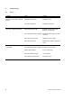
15. Special Servicing Tools New Special Tools No. Part Name Part No. Application 1 2 3 4 Test flange Locking strip Sleeve Installing tool - Puller 1130 - Installer 1130 Combination wrench 1139 893 2500 0000 893 5904 5910 893 1707 1123 890 2202 0000 890 3400 Leakage test Blocking the crankshaft For installing tool 10 Installing oil pump Removing oil pump Installing oil pump Various operations on the machine 5 Rem. Existing Special Tools No. Part Name Part No.
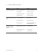
No. Part Name Part No. Application Rem. 17 18 19 20 21 Puller - Jaws (No. 3.1 profile) - Jaws (No.
16. Servicing Aids No. Part Name Part No. Application 1 Lubricating grease (225 g tube) 0781 120 1111 Oil seals, sliding and bearing points 2 STIHL special lubricant 0781 417 1315 Bearing bore in rope rotor, rewind spring in fan housing 3 STIHL Press Fluid OH 723 0781 957 9000 Rubber elements, fuel hoses, etc.
englisch / english 0455 533 0123. VA0.K12.