
Installation Guide
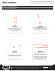


Stinger ELEV8 or HEIGH10® Radio Replacement Kit
for Jeep Wrangler JL and Jeep Gladiator JT Vehicles
SRK-JW18EH
© 2020 AAMP Global. All rights reserved. PAC is a Power Brand of AAMP Global.
AAMP Global is not aliated with FCA US LLC. Jeep® is a registered trademark of FCA US LLC. The terms
OEM, Jeep®, Wrangler®, and Gladiator® all terms are used strictly for identication purposes only. It is not
implied that any part listed is a product of, or approved by, Fiat Chrysler Automobiles.
Pacific Accessory Corporation
Page 8
Rev: v3
Date:100620
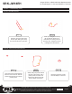
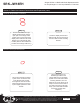
Section 3: Radio Unit Harness Connections and Preparation (cont.)
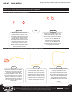
Connect one end of the 18” harness
(10P-2-10P-18) into either of the two
10-pin PAC Link ports on the RPA-
HD1 interface module. The other
end will be connected to the open
10-pin port on the PL1 interface
module after mounting the radio unit
into the vehicle.
Connect one end of the 6”
harness (10P-2-10P-6) into the
10-pin expansion port on the
CH4A-JW18 interface module,
then connect the other end into
either of the two 10-pin ports on
the PL1 interface module.
Part Two: 10P-2-10P Harness and HDMI Connections
Part One: Main Harness Connections (RPK-JW18-HAR) (cont.)
Step 5Step 4
Connect the white and red male
RCAs labeled “OEM AUX AUDIO”
on the RPK-JW18-HAR into the
white and red female RCAs
labeled “LINE IN / AUX IN” on the
A/V Stinger RCA harness.
Connect the 24-pin A/V Stinger
RCA harness (provided in the
Stinger radio box) into the 24-pin
port on the Stinger radio module.
Step 6
Connect the 6-pin SWI / IR harness
(provided in the Stinger radio box)
into the 6-pin port on the Stinger
radio module, then connect the
3.5mm jack labeled “STEERING
WHEEL CONTROL” on the RPK-
JW18-HAR into the female 3.5mm
connector labeled “SWI” on the
Stinger SWI / IR harness.
Connect one end of the 12” HDMI
cable into the HD OUT port on the
HD1 interface module. The other
end will be connected to the HDMI
input port on the Stinger radio
module after mounting the HD1
interface module into the vehicle.
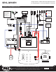
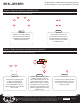
Step 1
Prior to making connections to the RPA-HD1 module,
verify that all 4 of the module’s DIP Switches are set to the
up position (OFF).
DIP SWITCHES LOCATED ON TOP
SIDE OF MODULE
Step 2 Step 3