
Datasheet


1.5KE Characteristics
Doc ID 2913 Rev 4 5/10
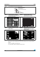
Figure 7. Capacitance versus reverse applied
voltage for bidirectional types
(typical values)
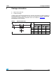
Figure 8. Peak forward voltage drop versus
peak forward current (typical values
for unidirectional types)
F
1 5001 10010
10
100
10
1000
10000
Multiply by 2 for units with V > 220 V
BR
500
100
10
1
00
.
5
11.
5
22.
533
.
5
44.
55
I
FM
(A)
V
FM
(V)
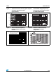
Figure 9. Transient thermal impedance
junction-ambient versus pulse
duration
Figure 10. Relative variation of leakage
current versus junction
temperature
Epoxy printed circuit board, FR4
copper thickness = 35 µm
t
p
(s)
Zth (j-a) (°C/W)
100
10
1
0.1
0.01 0.1 1 10 100 1000