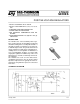
L78L00 SERIES POSITIVE VOLTAGE REGULATORS .. .. . . OUTPUT CURRENT UP TO 100 mA OUTPUT VOLTAGES OF 5; 6; 8; 9; 12; 15; 18; 24V THERMAL OVERLOAD PROTECTION SHORT CIRCUIT PROTECTION NO EXTERNAL COMPONENTS ARE REQUIRED AVAILABLE IN EITHER ± 5% (AC) OR ± 10% (C) SELECTION DESCRIPTION The L78L00 series of three-terminal positive regulators employ internal current limiting and thermal shutdown, making them essentially indestructible.
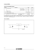
L78L00 SERIES ABSOLUTE MAXIMUM RATING Symbol Vi Io Parameter DC Input Voltage Unit 30 V V o = 12 V to 15 V 35 V V o = 18 V to 24 V 40 V 100 mA Output Current Ptot Power Dissipation Tstg Storage Temperature Range Top Value V o = 5 V to 9 V Operating Junction Temperature Range Internally limited (*) For L78L00C, L78L00AC For L78L00AB - 40 to 150 o C 0 to 125 - 40 to 125 o C C o (*) Our SO-8 package used for Voltage Regulators is modified internally to have pins 2, 3, 6 and 7 elec
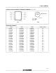
L78L00 SERIES CONNECTION DIAGRAM AND ORDERING NUMBERS (top view) BOTTOM VIEW pin 1 = OUT pin 2 = GND pin 3 = IN SO-8 TO-92 ORDERING NUMBERS Type L78L05C L78L05AC L78L05AB L78L06C L78L06AC L78L06AB L78L08C L78L08AC L78L08AB L78L09C L78L09AC L78L09AB L78L12C L78L12AC L78L12AB L78L15C L78L15AC L78L15AB L78L18C L78L18AC L78L18AB L78L24C L78L24AC L78L24AB SO-8 L78L05CD L78L05ACD L78L05ABD L78L06CD L78L06ACD L78L06ABD L78L08CD L78L08ACD L78L08ABD L78L09CD L78L09ACD L78L09ABD L78L12CD L78L12ACD L78L12ABD L78L
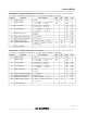
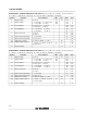
L78L00 SERIES ELECTRICAL CHARACTERISTICS FOR L78L05 (refer to the test circuits, T j = 0 to 125 o C, V i = 10V, Io = 40 mA, C i = 0.33 µF, C o = 0.1 µF unless otherwise specified) Symbol Parameter Test Conditions Min. Typ. Max. Unit 4.6 5 5.4 V 5.5 5.5 V V 200 150 mV mV 60 30 mV mV Tj = 25 oC Tj = 125 oC 6 5.5 mA mA Quiescent Current Change Io = 1 to 40 mA 0.2 mA ∆Id Quiescent Current Change Vi = 8 to 20 V 1.
L78L00 SERIES ELECTRICAL CHARACTERISTICS FOR L78L08 (refer to the test circuits, T j = 0 to 125 o C, V i = 14V, Io = 40 mA, C i = 0.33 µF, C o = 0.1 µF unless otherwise specified) Symbol Parameter Test Conditions Min. Typ. Max. Unit 7.36 8 8.64 V 8.8 8.8 V V 200 150 mV mV 80 40 mV mV Tj = 25 oC Tj = 125 oC 6 5.5 mA mA Quiescent Current Change Io = 1 to 40 mA 0.2 mA ∆Id Quiescent Current Change Vi = 11 to 23 V 1.
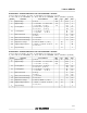
L78L00 SERIES ELECTRICAL CHARACTERISTICS FOR L78L12 (refer to the test circuits, T j = 0 to 125 o C, V i = 19V, Io = 40 mA, C i = 0.33 µF, C o = 0.1 µF unless otherwise specified) Symbol Parameter Test Conditions Min. Typ. Max. Unit 11.1 12 12.9 V 13.2 13.2 V V 250 200 mV mV 100 50 mV mV Tj = 25 oC Tj = 125 oC 6.5 6 mA mA Quiescent Current Change Io = 1 to 40 mA 0.2 mA ∆Id Quiescent Current Change Vi = 16 to 27 V 1.
L78L00 SERIES ELECTRICAL CHARACTERISTICS FOR L78L18 (refer to the test circuits, T j = 0 to 125 o C, V i = 27V, Io = 40 mA, C i = 0.33 µF, C o = 0.1 µF unless otherwise specified) Symbol Parameter Test Conditions Min. Typ. Max. Unit 16.6 18 19.4 V 19.8 19.8 V V 320 270 mV mV 170 85 mV mV Tj = 25 oC Tj = 125 oC 6.5 6 mA mA Quiescent Current Change Io = 1 to 40 mA 0.2 mA ∆Id Quiescent Current Change Vi = 23 to 33 V 1.
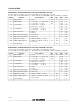
L78L00 SERIES ELECTRICAL CHARACTERISTICS FOR L78L05AB AND L78L05AC (refer to the test circuits, Vi = 10V, I o = 40 mA, C i = 0.33 µF, C o = 0.1 µF, T j = 0 to 125 o C for L78L05AC, T j = -40 to 125 o C for L78L05AB, unless otherwise specified) Symbol Parameter Test Conditions Min. Typ. Max. Unit 4.8 5 5.2 V 5.25 5.25 V V 150 100 mV mV 60 30 mV mV Tj = 25 oC Tj = 125 oC 6 5.5 mA mA Quiescent Current Change Io = 1 to 40 mA 0.1 mA ∆Id Quiescent Current Change Vi = 8 to 20 V 1.
L78L00 SERIES ELECTRICAL CHARACTERISTICS FOR L78L08AB AND L78L08AC (refer to the test circuits, Vi = 14V, I o = 40 mA, C i = 0.33 µF, C o = 0.1 µF, T j = 0 to 125 o C for L78L08AC, T j = -40 to 125 o C for L78L08AB, unless otherwise specified) Symbol Parameter Test Conditions Min. Typ. Max. Unit 7.68 8 8.32 V 8.4 8.4 V V 175 125 mV mV 80 40 mV mV Tj = 25 oC Tj = 125 oC 6 5.5 mA mA Quiescent Current Change Io = 1 to 40 mA 0.1 mA ∆Id Quiescent Current Change Vi = 11 to 23 V 1.
L78L00 SERIES ELECTRICAL CHARACTERISTICS FOR L78L12AB AND L78L12AC (refer to the test circuits, Vi = 19V, I o = 40 mA, C i = 0.33 µF, C o = 0.1 µF, T j = 0 to 125 o C for L78L12AC, T j = -40 to 125 o C for L78L12AB, unless otherwise specified) Symbol Parameter Test Conditions Min. Typ. Max. Unit 11.5 12 12.5 V 12.6 12.6 V V 250 200 mV mV 100 50 mV mV Tj = 25 oC Tj = 125 oC 6.5 6 mA mA Quiescent Current Change Io = 1 to 40 mA 0.1 mA ∆Id Quiescent Current Change Vi = 16 to 27 V 1.
L78L00 SERIES ELECTRICAL CHARACTERISTICS FOR L78L18AB AND L78L18AC (refer to the test circuits, Vi = 27V, I o = 40 mA, C i = 0.33 µF, C o = 0.1 µF, T j = 0 to 125 o C for L78L18AC, T j = -40 to 125 o C for L78L18AB, unless otherwise specified) Symbol Parameter Test Conditions Min. Typ. Max. Unit 17.3 18 18.7 V 18.9 18.9 V V 320 270 mV mV 170 85 mV mV Tj = 25 oC Tj = 125 oC 6.5 6 mA mA Quiescent Current Change Io = 1 to 40 mA 0.1 mA ∆Id Quiescent Current Change Vi = 23 to 33 V 1.
L78L00 SERIES Figure 1: L78L05/12 Output Voltage vs Ambient Temperature Figure 2 : L78L05/12/24 Load Characteristics. Figure 3 : L78L05/12/24 Thermal Shutdown. Figure 4 : L78L05/12 Quiescent Current vs Output Current Figure 5 : L78L05 Quiescent Current vs Input Voltage. Figure 6 : L78L05/12/24 Output Characteristics.
L78L00 SERIES Figure 7 : L78L05/12/24 Ripple Rejection. Figure 8 : L78L05 Dropout Characteristics. Figure 9 : L78L00 Series Short Circuit Output Current.
L78L00 SERIES Figure 11 : Output Boost Circuit. Figure 12 : Current Regulator.
L78L00 SERIES SO8 MECHANICAL DATA mm DIM. MIN. TYP. A a1 inch MAX. MIN. TYP. 1.75 0.1 0.068 0.25 a2 MAX. 0.003 0.009 1.65 0.064 a3 0.65 0.85 0.025 0.033 b 0.35 0.48 0.013 0.018 b1 0.19 0.25 0.007 0.010 C 0.25 0.5 0.010 0.019 c1 45° (typ.) D 4.8 5.0 0.188 0.196 E 5.8 6.2 0.228 0.244 e 1.27 0.050 e3 3.81 0.150 F 3.8 4.0 0.14 0.157 L 0.4 1.27 0.015 0.050 M S 0.6 0.023 8° (max.
L78L00 SERIES TO-92 MECHANICAL DATA mm inch DIM. MIN. TYP. MAX. MIN. TYP. A 4.58 5.33 0.180 0.210 B 4.45 5.2 0.175 0.204 C 3.2 4.2 0.126 0.165 D 12.7 0.500 E 1.27 F 0.4 G 0.35 0.050 0.51 0.016 0.020 0.14 D G F E B E A C G 16/17 MAX.
L78L00 SERIES Information furnished is believed to be accurate and reliable. However, SGS-THOMSON Microelectronics assumes no responsability for the consequences of use of such information nor for any infringement of patents or other rights of third parties which may results from its use. No license is granted by implication or otherwise under any patent or patent rights of SGS-THOMSON Microelectronics. Specifications mentioned in this publication are subject to change without notice.