
Datasheet

A5972D Closing the loop
Doc ID 13956 Rev 5 15/37
whereas the zero is defined as:
Equation 5
F
P1
is the low frequency which sets the bandwidth, while the zero F
Z1
is usually put near to
the frequency of the double pole of the L-C filter (see below). F
P2
is usually at a very high
frequency.
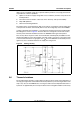
7.2 LC filter
The transfer function of the L-C filter is given by:
Equation 6
where R
LOAD
is defined as the ratio between V
OUT
and I
OUT
.
If R
LOAD
>>ESR, the previous expression of A
LC
can be simplified and becomes:
Equation 7
The zero of this transfer function is given by:
Equation 8
F
0
is the zero introduced by the ESR of the output capacitor and it is very important to
increase the phase margin of the loop.
The poles of the transfer function can be calculated through the following expression:
Equation 9
In the denominator of A
LC
the typical second order system equation can be recognized:
Equation 10
F
Z1
1
2 π• R
c
• C
c
•
-------------------------------------=
A
LC
s()
R
LOAD
1 ESR C
OUT
s••+()•
s
2
LC
OUT
ESR R
LOAD
+()s ESR C
OUT
• R
LOAD
L+•()R
LOAD
+•+•••
----------------------------------------------------------------------------------------------------------------------------------------------------------------------------------------------------=
A
LC
s()
1 ESR C
OUT
• s•+
LC
OUT
• s
2
ESR C
OUT
• s1+•+•
----------------------------------------------------------------------------------------------=
F
O
1
2 π• ESR• C
OUT
•
--------------------------------------------------- -=
F
PLC1 2,
ESR C
OUT
ESR C
OUT
•()
2
4L• C
OUT
•–±•–
2L• C
OUT
•
------------------------------------------------------------------------------------------------------------------------------------------=
s
2
2 δ•ω
n
• s ω
2
n
+•+