
Datasheet


Application information A5972D
30/37 Doc ID 13956 Rev 5
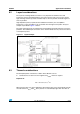
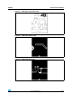
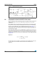
Figure 21. Negative buck-boost regulator
8.8 Compensation network with MLCC at the output
MLCCs (multiple layer ceramic capacitor) with values in the range of 10 µF-22 µF and rated
voltages in the range of 10 V-25 V are available today at relatively low cost from many
manufacturers.
These capacitors have very low ESR values (a few mΩ) and thus are occasionally used for
the output filter in order to reduce the voltage ripple and the overall size of the application.
However, a very low ESR value affects the compensation of the loop (see Section 7) and in
order to keep the system stable, a more complicated compensation network may be
required. However, due to the architecture of the internal error amplifier the bandwidth with
this compensation is limited.
That is why output capacitors with a not negligible ESR are suggested. The selection of the
output capacitor have to guarantee that the zero introduced by this component is inside the
designed system bandwidth and close to the frequency of the double pole introduced by the
LC filter. A general rule for the selection of this compound for the system stability is provided
in Equation 41.
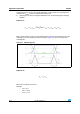
Equation 41
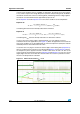
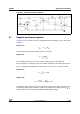
The figure below shows an example of a compensation network stabilizing the system with
ceramic capacitors at the output (the optimum component value depends on the
application).
f
Z ESR
1
2 π ESR C
OUT
⋅⋅ ⋅
------------------------------------------------= bandwidth<
f
LC
f<
Z ESR
10 f
LC
⋅<