
User's Manual
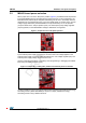
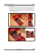
Table Of Contents

Hardware and layout description UM1589
10/19 DocID023883 Rev 3
Figure 6 and Figure 7 illustrate the use of an external antenna using the ANT1-M24LR16E
demonstration board.
• Figure 6 shows a possible direct connection of the Vout voltage coming from the ANT1-
M24LR16E antenna demo board on jumper JP1 to bypass the voltage regulator (U5).
• Figure 7 shows the connection of the Vout voltage coming from the ANT1-M24LR16E
antenna demo board on connector CN2 to use the voltage regulator (U5). Jumper JP1
must be set as shown in Figure 5.
Figure 6. External antenna connection with voltage regulator bypass
Figure 7. External antenna connection using M24LR board voltage regulator