
User's Manual
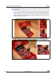
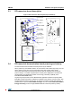
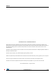
Table Of Contents

DocID023883 Rev 3 11/19
UM1589 Hardware and layout description
3.3 RF transceiver board description
Figure 8. RF transceiver board layout (top and bottom)
3.4 RF transceiver demonstration board powering and startup
The RF transceiver demonstration board is powered by the USB bus.
When powered up, the CR95HF starts in an autonomous mode called “tag hunting”: the red
LED 1 lights up every time a tag is recognized. During Tag Hunting mode, the RF
transceiver demonstration board switches ON and OFF the magnetic field at each RF
protocol change. A constant magnetic field is naturally more appropriate to evaluate and
develop battery-less applications based on the Energy Harvesting capability of the
M24LRXXE-R EEPROM Family.
Tag Hunting mode persists until the M24LR/CR95 application software setup file [STSW-
M24LR011] is launched and the CR95HF is initialized by the software. At this moment, both
Tag Hunting mode and the RF field stop. To activate a constant magnetic field emission, it
possible either to open the Demo NDEF messages menu and select Show Demo NDEF &
Energy Harvesting or send a single ISO/IEC15693 RF command (Inventory, Read.).
2-turn,13.56-MHz
loop antenna
Reset button
27.12-MHz
crystal oscillator
20-pin JTAG
connector (J3)
STM32F103CBT6
User LED 1
LDO regulator
USB
connector (J1)
CR95HF RF IC