
User's Manual
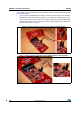
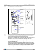
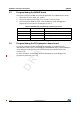
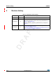
Table Of Contents

Hardware and layout description UM1589
12/19 DocID023883 Rev 3
3.5 Program/debug the M24LR board
To program or debug an STM8L microcontroller application on the M24LR board, simply:
1. Set jumper JP1 in the “REG_3V3” position.
2. Connect an external power supply to the “3V3-6V” connector (CN2).
3. Connect the 4-pin SWIM connector of the STLINK/V2 in-circuit debugger and
programmer to connector CN1 as described in Table 3.
3.6 Program/debug the RF transceiver demo board
To program or debug an STM32 microcontroller application on the RF transceiver
demonstration board, simply connect the 20-pin JTAG/SWD flat ribbon of the STLINK/V2 in-
circuit debugger and programmer to the RF transceiver demonstration board JTAG
connector (J2).
For more information, documentation about the STLINK/V2 in-circuit debugger and
programmer, please visit
www.st.com.
Table 3. M24LR board programming and debug connector
Pin CN2 Designation
1 Vcc VDD supply from M24LR board
2 PA0 SWIM data input/output
3 GND Ground supply
4 RESET SWIM reset