
User's Manual
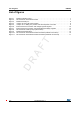
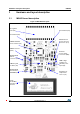
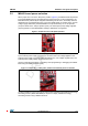
Table Of Contents

Hardware and layout description UM1589
8/19 DocID023883 Rev 3
3 Hardware and layout description
3.1 M24LR board description
Figure 3. M24LR board layout
STM8L152C6T6
SWIM connector
M24LR04E-R
4-MHz crystal
M24LR04E-R
9-turn,
Reset button (B1)
M24LR board
External
LDO voltage
STTS751 I²C
temperature
sensor (U2)
regulator for
external power
input (U5)
power supply
connector (CN2)
power selection
connector (JP1)
13.56-MHz
etched loop
antenna
Dual interface
EEPROM (U4)
oscillator (X1)
and I²C
connector (CN3)
(CN1)
microcontroller (U1)
24-segment
LCD (U3)
User button (B2)