
User's Manual
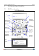
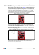
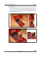
Table Of Contents

DocID023883 Rev 3 9/19
UM1589 Hardware and layout description
3.2 M24LR board power selection
When jumper JP1 is set in the “RF power” position (Figure 4), the M24LR board is powered
by the M24LR04E-R energy harvesting analog output (Vout pin). In this configuration, the
M24LR board is powered by the magnetic field flowing into its 9-turn, etched loop antenna,
delivered from a 13.56-MHz RF source, such as an RFID reader or an NFC phone. The DC
voltage supply delivered by the M24LR04E-R Vout pin is filtered by an 10-nF capacitor
(C19) and stored in the 150-µF capacitor (C22). The low dropout (LDO) voltage regulator
(U5) is bypassed, so the M24LR04E-R voltage is filtered but not regulated.
Figure 4. Jumper JP1 set in RF power position
When jumperJP1 is set in the “REG 3.3" position (Figure 5), the M24LR board is powered
by the external power supply connected on connector CN2. The voltage applied on the
external power supply connector CN2 is regulated by the 3.3V voltage regulator (U5). The
external power supply voltage can be from 3.3 to 6V.
Using an external power supply is necessary when programming or debugging the STM8L
MCU using the SWIM connector (CN1).
Figure 5. Jumper JP1 in “REG_3V3” position and external power connection
It is also possible to connect an external antenna demonstration board featuring the energy
harvesting function (ANTX-M24LRXXE) to improve or simply evaluate the energy
harvesting function using a different antenna.