
Datasheet


3/31
STE100P
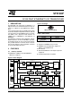
3 PIN ASSIGNMENT DIAGRAM
Figure 4. Pin Connection
4 PIN DESCRIPTION
Table 2. Pin Description
Pin No. Name Type Description
MII Data Interface
52
58
57
56
55
txd4
txd3
txd2
txd1
txd0
I Transmit Data. The Media Access Controller (MAC) drives data to the STE100P
using these inputs.
txd4 is monitored only in Symbol (5B) Mode.
These signals must be synchronized to the tx_clk.
54 tx_en I Transmit Enable. The MAC asserts this signal when it drives valid data on the
txd inputs. This signal must be synchronized to the tx_clk.
53 tx_clk I/O Transmit Clock. Normally the STE100P drives tx_clk. Refer to the Clock
Requirements discussion in the Functional Description section.
25 MHz for 100 Mbps operation.
2.5 MHz for 10 Mbps operation.
1
2
3
5
6
4
7
8
9
10
27
11
28 29 30 31 32
59 58 57 56
54
55 53 52 51 50 49
43
42
41
39
38
40
48
47
46
44
45
fde
mf0
mf1
mf3
mf4
mf2
x2
gnda
vcca
gnda
nc
vcca
txn
gnda
gnde
pwrdwn
test
reset
rip
nc
nc
nc
col
txd3
txd2
txd1
tx_en
txd0
tx_clk
tx_er/txd4
rx_er/rxd4
gnde/i
rx_clk
rdx3
mdc
mdio
vcce/i
ledr10
gnde/i
rx_dv
rxd0
rxd1
rdx2
vcce/i
D99TL457B
22 23 24 25 26
60
crs
61
mdint
62
vcce/i
63
cfg1
64
cfg0
vcca
rxn
rxp
gnda
txp
17 18 19 20 21
37
36
34
33
35
ledtr
ledl
leds
test_se
ledc
12
13
14
15
16
vcca
iref
gnda
x1
vcca