
Datasheet
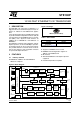


STE100P
8/31
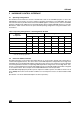
6 REGISTERS AND DESCRIPTORS DESCRIPTION
There are 11 registers with 16 bits each supported for the STE100P. These include 7 basic registers which
are defined according to the clause 22 “Reconciliation Sublayer and Media Independent Interface” and
clause 28 “Physical Layer link signaling for 10 Mb/s and 100 Mb/s Auto-Negotiation on twisted pair” of
IEEE802.3u standard.
In addition, there are 4 special registers for advanced chip control and status information.
6.1 Register List
Table 4. Register List
6.2 Register Descriptions
Address Reg. Index Name Register Descriptions
0 PR0 XCR XCVR Control Register
1 PR1 XSR XCVR Status Register
2 PR2 PID1 PHY Identifier 1
3 PR3 PID2 PHY Identifier 2
4 PR4 ANA Auto-Negotiation Advertisement Register
5 PR5 ANLPA Auto-Negotiation Link Partner Ability Register
6 PR6 ANE Auto-Negotiation Expansion Register
17 PR17 XCIIS XCVR Configuration Information and Interrupt Status Register
18 PR18 XIE XCVR Interrupt Enable Register
19 PR19 100CTR 100Base-TX PHY Control/Status Register
20 PR20 XMC XCVR Mode Control Register
Table 5. Register Descriptions
Bit # Name Descriptions Default Val RW Type
PR0- XCR, XCVR Control Register. The default values on power-up/reset are as listed below.
15 XRST Reset control.
1: Device will be reset. This bit will be cleared by STE100P
itself after the reset is completed.
0R/W
14 XLBEN Loop-back mode select.
1: Loop-back mode is selected.
0: Normal mode
0R/W
13 SPSEL Network Speed select. This bit’s selection will be ignored if
Auto-Negotiation is enabled(bit 12 of PR0 = 1).
1:100Mbps is selected.
0:10Mbps is selected.
1R/W
12 ANEN Auto-Negotiation ability control.
1: Auto-Negotiation function is enabled.
0: Auto-Negotiation is disabled.
1R/W