
Datasheet


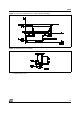


PIN FUNCTIONS (refer to the block diagram)
MW.15 PowerSO Name Function
1;15 2;19 Sense A; Sense B Between this pin and ground is connected the sense resistor to
control the current of the load.
2;3 4;5 Out 1; Out 2 Outputs of the Bridge A; the current that flows through the load
connected between these two pins is monitored at pin 1.
46 V
S
Supply Voltage for the Power Output Stages.
A non-inductive 100nF capacitor must be connected between this
pin and ground.
5;7 7;9 Input 1; Input 2 TTL Compatible Inputs of the Bridge A.
6;11 8;14 Enable A; Enable B TTL Compatible Enable Input: the L state disables the bridge A
(enable A) and/or the bridge B (enable B).
8 1,10,11,20 GND Ground.
9 12 VSS Supply Voltage for the Logic Blocks. A100nF capacitor must be
connected between this pin and ground.
10; 12 13;15 Input 3; Input 4 TTL Compatible Inputs of the Bridge B.
13; 14 16;17 Out 3; Out 4 Outputs of the Bridge B. The current that flows through the load
connected between these two pins is monitored at pin 15.
– 3;18 N.C. Not Connected
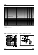
ELECTRICAL CHARACTERISTICS (V
S
= 42V; V
SS
= 5V, T
j
= 25°C; unless otherwise specified)
Symbol Parameter Test Conditions Min. Typ. Max. Unit
V
S
Supply Voltage (pin 4) Operative Condition V
IH
+2.5 46 V
V
SS
Logic Supply Voltage (pin 9) 4.5 5 7 V
I
S
Quiescent Supply Current (pin 4) V
en
= H; I
L
= 0 V
i
= L
V
i
= H
13
50
22
70
mA
mA
V
en
= L V
i
= X 4 mA
I
SS
Quiescent Current from V
SS
(pin 9) V
en
= H; I
L
= 0 V
i
= L
V
i
= H
24
7
36
12
mA
mA
V
en
= L V
i
= X 6 mA
V
iL
Input Low Voltage
(pins 5, 7, 10, 12)
–0.3 1.5 V
V
iH
Input High Voltage
(pins 5, 7, 10, 12)
2.3 VSS V
I
iL
Low Voltage Input Current
(pins 5, 7, 10, 12)
V
i
= L –10
µ
A
I
iH
High Voltage Input Current
(pins 5, 7, 10, 12)
Vi = H
≤
V
SS
–0.6V
30 100
µ
A
V
en
= L Enable Low Voltage (pins 6, 11) –0.3 1.5 V
V
en
= H Enable High Voltage (pins 6, 11) 2.3 V
SS
V
I
en
= L Low Voltage Enable Current
(pins 6, 11)
V
en
= L –10
µ
A
I
en
= H High Voltage Enable Current
(pins 6, 11)
V
en
= H
≤
V
SS
–0.6V
30 100
µ
A
V
CEsat (H)
Source Saturation Voltage I
L
= 1A
I
L
= 2A
0.95 1.35
2
1.7
2.7
V
V
V
CEsat (L)
Sink Saturation Voltage I
L
= 1A (5)
I
L
= 2A (5)
0.85 1.2
1.7
1.6
2.3
V
V
V
CEsat
Total Drop I
L
= 1A (5)
I
L
= 2A (5)
1.80 3.2
4.9
V
V
V
sens
Sensing Voltage (pins 1, 15) –1 (1) 2 V
L298
3/13