
Datasheet


5/13
L6920
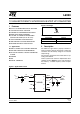
3 Detailed Description
The L6920 is a high efficiency, low voltage step-up DC/DC converter particularly suitable for 1 to 3 cells (Li-Ion/
polymer, NiMH respectively) battery up conversion.
These performances are achieved via a strong reduction of quiescent current (10
µ
A only) and adopting a syn-
chronous rectification, that implies also a reduced cost in the application (no external diode required).
Operation is based on maximum ON time - minimum OFF time control, tailored by a current limit set to 1A. A
simplified block diagram is shown here below.
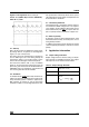
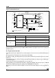
Figure 6. Simplified Block Diagram
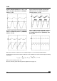
4 Principle of Operation
In L6920 the control is based on a comparator that continuously checks the status of output voltage.
If the output voltage is lower than the expected value, the control function of the L6920 directs the energy stored
in the inductor to be transferred to the load. This is accomplished by alternating between two basic steps:
- TON phase: the energy is transferred from the battery to the inductor by shorting LX node to ground via the N-
channel power switch. The switch is turned off if the current flowing in the inductor reaches 1A or after a max-
imum on time set to 5
µ
s.
- TOFF phase: the energy stored in the inductor is transferred to the load through the synchronous switch for at
least a minimum off time equal to 1
µ
s. After this, the synchronous switch is turned off as soon as the output
voltage goes lower than the regulated voltage or the current flowing in the inductor goes down to zero.
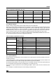
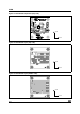
So, in case of light load, the device works in PFM mode, as shown in figures 7 to 10.
R
Q
S
Ton max
5µsec
Toff min
1µsec
VBG
VBG
VBG
A
B
C
-
+
-
+
-
+
-
+
-
+
VOUT
ZERO CROSSING
OPAMP
(CR)
CURRENT LIMIT
OUT
FB
GND
V
REF
LBI
LBO
D99IN1041
SHDN
LX
V
IN
V
OUT
V
OUT
GND
R
1
,R
2
FB Y
Y
A
B
C
- +