
Datasheet
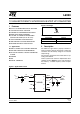


L6920
6/13
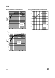
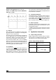
Figure 7.
PFM mode Condition: V
out
= 5V; V
in
=1.5V.
Trace1: Vout (50mV~/div) Trace 4: IL (100mA/div)
Time div.: 5
µ
s/div
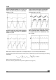
Figure 8.
Heavier load - Train pulses overlapping.
Trace1: V
out
(100mV~/div) Trace 4: I
L
(200mA/div)
Time div.: 10
µ
s/div
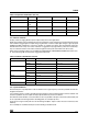
Figure 9.
Heavy load - Inductor current ripples
below I
lim
Trace1: V
out
(100mV~/div)
Trace 4: I
L
(200mA/div) Time div.: 20
µ
s/div
Figure 10.
Heavy load and High ESR. Regulation
falls in continuous mode of operation. Trace1:
V
out
(100mV~/div) Trace 4: I
L
(200mA/div). Time
div.: 5
µ
s/div
When Iload is heavier, the pulse trains are overlapped. Figures 7 - 8 show some possible behaviors.
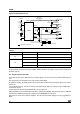
Considering that current in the inductor is limited to 1A, the maximum load current is defined by the following
relationship:
eq. (1)
Where
η
is the efficiency and I
lim
=1A.
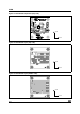
Of course, if Iload is greater than Iload_lim the regulation is lost (figure 11).
I
load_lim
V
in
V
out
-----------
I
lim
T
off min
–
V
out
V
in
–
2L⋅
--------------------------
⋅
⎝⎠
⎛⎞
η⋅⋅=