
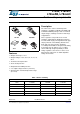
Datasheet

DocID2143 Rev 31 9/57
L78xx, L78xxC, L78xxAB, L78xxAC Electrical characteristics
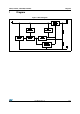
5 Electrical characteristics
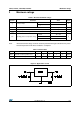
Refer to the test circuits, T
J
= -55 to 150 °C, V
I
= 10 V, I
O
= 500 mA, C
I
= 0.33 µF,
C
O
= 0.1 µF unless otherwise specified.
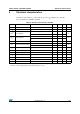
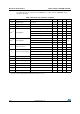
Table 4. Electrical characteristics of L7805
Symbol Parameter Test conditions Min. Typ. Max. Unit
V
O
Output voltage T
J
= 25°C 4.8 5 5.2 V
V
O
Output voltage I
O
= 5 mA to 1 A, V
I
= 8 to 20 V 4.65 5 5.35 V
V
O
(1)
Line regulation
V
I
= 7 to 25 V, T
J
= 25°C 3 50
mV
V
I
= 8 to 12 V, T
J
= 25°C 1 25
V
O
(1)
Load regulation
I
O
= 5 mA to 1.5 A, T
J
= 25°C 100
mV
I
O
= 250 to 750 mA, T
J
= 25°C 25
I
d
Quiescent current T
J
= 25°C 6 mA
I
d
Quiescent current change
I
O
= 5 mA to 1 A 0.5
mA
V
I
= 8 to 25 V 0.8
V
O
/T Output voltage drift I
O
= 5 mA 0.6 mV/°C
eN Output noise voltage B =10 Hz to 100 kHz, T
J
= 25°C 40 µV/V
O
SVR Supply voltage rejection V
I
= 8 to 18 V, f = 120 Hz 68 dB
V
d
Dropout voltage I
O
= 1 A, T
J
= 25°C 2 2.5 V
R
O
Output resistance f = 1 kHz 17 m
I
sc
Short circuit current V
I
= 35 V, T
J
= 25°C 0.75 1.2 A
I
scp
Short circuit peak current T
J
= 25°C 1.3 2.2 3.3 A
1. Load and line regulation are specified at constant junction temperature. Changes in V
O
due to heating effects must be
taken into account separately. Pulse testing with low duty cycle is used.