L79 Negative voltage regulators Datasheet - production data Description TO-220 The L79 series of three-terminal negative regulators is available in TO-220, TO-220FP and D²PAK packages and several fixed output voltages, making it useful in a wide range of applications.
Contents L79 Contents 1 Diagram . . . . . . . . . . . . . . . . . . . . . . . . . . . . . . . . . . . . . . . . . . . . . . . . . . . 3 2 Pin configuration . . . . . . . . . . . . . . . . . . . . . . . . . . . . . . . . . . . . . . . . . . . 4 3 Maximum ratings . . . . . . . . . . . . . . . . . . . . . . . . . . . . . . . . . . . . . . . . . . . . 5 4 Test circuit . . . . . . . . . . . . . . . . . . . . . . . . . . . . . . . . . . . . . . . . . . . . . . . . . 6 5 Electrical characteristics . . .
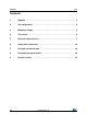
L79 1 Diagram Diagram Figure 1.
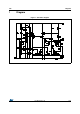
Pin configuration 2 L79 Pin configuration Figure 2.
L79 Maximum ratings 3 Maximum ratings Table 2. Absolute maximum ratings Symbol Parameter Value Unit -35 V VI DC input voltage IO Output current Internally limited PD Power dissipation Internally limited TSTG Storage temperature range TOP Operating junction temperature range Note: -65 to 150 for L79xxC 0 to 150 for L79xxAC 0 to 125 °C °C Absolute maximum ratings are those values beyond which damage to the device may occur. Functional operation under these condition is not implied.
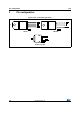
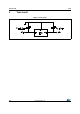
Test circuit 4 L79 Test circuit Figure 3.
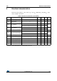
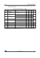
L79 Electrical characteristics 5 Electrical characteristics Refer to the test circuits, TJ = 0 to 125 °C, VI = -10 V, IO = 500 mA, CI = 2.2 µF, CO = 1 µF unless otherwise specified. Table 4. Electrical characteristics of L7905AC Symbol Parameter Test conditions Min. Typ. Max. Unit VO Output voltage TJ = 25°C -4.9 -5 -5.1 V VO Output voltage IO = -5 mA to -1 A, PO ≤ 15 W VI = -8 to -20 V -4.8 -5 -5.
Electrical characteristics L79 Refer to the test circuits, TJ = 0 to 125 °C, VI = -10 V, IO = 500 mA, CI = 2.2 µF, CO = 1 µF unless otherwise specified. Table 5. Electrical characteristics of L7905C Symbol Parameter Test conditions Min. Typ. Max. Unit VO Output voltage TJ = 25°C -4.8 -5 -5.2 V VO Output voltage IO = -5 mA to -1 A, PO ≤ 15 W VI = -8 to -20 V -4.75 -5 -5.
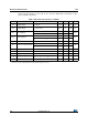
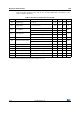
L79 Electrical characteristics Refer to the test circuits, TJ = 0 to 125 °C, VI = -14 V, IO = 500 mA, CI = 2.2 µF, CO = 1 µF unless otherwise specified. Table 6. Electrical characteristics of L7908C Symbol Parameter Test conditions Min. Typ. Max. Unit VO Output voltage TJ = 25°C -7.7 -8 -8.3 V VO Output voltage IO = -5 mA to -1 A, PO ≤ 15 W VI = -11.5 to -23 V -7.6 -8 -8.
Electrical characteristics L79 Refer to the test circuits, TJ = 0 to 125 °C, VI = -19 V, IO = 500 mA, CI = 2.2 µF, CO = 1 µF unless otherwise specified. Table 7. Electrical characteristics of L7912AC Symbol Parameter Test conditions Min. Typ. Max. Unit VO Output voltage TJ = 25°C -11.75 -12 -12.25 V VO Output voltage IO = -5 mA to -1 A, PO ≤ 15 W VI = -15.5 to -27 V -11.5 -12 -12.
L79 Electrical characteristics Refer to the test circuits, TJ = 0 to 125 °C, VI = -19 V, IO = 500 mA, CI = 2.2 µF, CO = 1 µF unless otherwise specified. Table 8. Electrical characteristics of L7912C Symbol Parameter Test conditions Min. Typ. Max. Unit VO Output voltage TJ = 25°C -11.5 -12 -12.5 V VO Output voltage IO = -5 mA to -1 A, PO ≤ 15 W VI = -15.5 to -27 V -11.4 -12 -12.
Electrical characteristics L79 Refer to the test circuits, TJ = 0 to 125 °C, VI = -23 V, IO = 500 mA, CI = 2.2 µF, CO = 1 µF unless otherwise specified. Table 9. Electrical characteristics of L7915AC Symbol Parameter Test conditions Min. Typ. Max. Unit VO Output voltage TJ = 25°C -14.7 -15 -15.3 V VO Output voltage IO = -5 mA to -1 A, PO ≤ 15 W VI = -18.5 to -30 V -14.4 -15 -15.
L79 Electrical characteristics Refer to the test circuits, TJ = 0 to 125 °C, VI = -23 V, IO = 500 mA, CI = 2.2 µF, CO = 1 µF unless otherwise specified. Table 10. Electrical characteristics of L7915C Symbol Parameter Test conditions Min. Typ. Max. Unit VO Output voltage TJ = 25°C -14.4 -15 -15.6 V VO Output voltage IO = -5 mA to -1 A, PO ≤ 15 W VI = -18.5 to -30 V -14.3 -15 -15.
Application information 6 L79 Application information Figure 4. Fixed output regulator Note: CI is required for stability. For value given, capacitor must be solid tantalum. If aluminium electrolytic are used, at least ten times value should be selected. CO is required if regulator is located an appreciable distance from power supply filter. To improve transient response.
L79 Application information Figure 6. Circuit for increasing output voltage 92 9;; 5 5 5 9;; 5 ! ,G *1' *1 ,1 ,1 / 287 C3 Optional for improved transient response and ripple rejection. Figure 7.
Package mechanical data 7 L79 Package mechanical data In order to meet environmental requirements, ST offers these devices in different grades of ECOPACK® packages, depending on their level of environmental compliance. ECOPACK® specifications, grade definitions and product status are available at: www.st.com. ECOPACK® is an ST trademark. Figure 8.
L79 Package mechanical data Table 11. TO-220 (single gauge) mechanical data mm Dim. Min. Typ. Max. A 4.40 4.60 b 0.61 0.88 b1 1.14 1.70 c 0.48 0.70 D 15.25 15.75 E 10 10.40 e 2.40 2.70 e1 4.95 5.15 F 0.51 0.60 H1 6.20 6.60 J1 2.40 2.72 L 13 14 L1 3.50 3.93 L20 16.40 L30 28.90 ∅P 3.75 3.85 Q 2.65 2.
Package mechanical data L79 Figure 9.
L79 Package mechanical data Table 12. TO-220 (dual gauge) mechanical data mm Dim. Min. Typ. Max. A 4.40 4.60 b 0.61 0.88 b1 1.14 1.70 c 0.48 0.70 D 15.25 15.75 D1 1.27 E 10 10.40 e 2.40 2.70 e1 4.95 5.15 F 1.23 1.32 H1 6.20 6.60 J1 2.40 2.72 L 13 14 L1 3.50 3.93 L20 16.40 L30 28.90 ∅P 3.75 3.85 Q 2.65 2.
Package mechanical data L79 Figure 10.
L79 Package mechanical data Table 13. TO-220FP mechanical data mm Dim. Min. Typ. Max. A 4.4 4.6 B 2.5 2.7 D 2.5 2.75 E 0.45 0.7 F 0.75 1 F1 1.15 1.70 F2 1.15 1.70 G 4.95 5.2 G1 2.4 2.7 H 10 10.4 L2 16 L3 28.6 30.6 L4 9.8 10.6 L5 2.9 3.6 L6 15.9 16.4 L7 9 9.3 Dia 3 3.
Package mechanical data L79 Figure 11.
L79 Package mechanical data Table 14. D²PAK mechanical data mm Dim. Min. Typ. Max. A 4.40 4.60 A1 0.03 0.23 b 0.70 0.93 b2 1.14 1.70 c 0.45 0.60 c2 1.23 1.36 D 8.95 9.35 D1 7.50 E 10 E1 8.50 10.40 e 2.54 e1 4.88 5.28 H 15 15.85 J1 2.49 2.69 L 2.29 2.79 L1 1.27 1.40 L2 1.30 1.75 R V2 0.
Package mechanical data L79 Figure 12. D²PAK footprint(a) 16.90 12.20 5.08 1.60 3.50 9.75 a. All dimensions are in millimeters.
L79 8 Packaging mechanical data Packaging mechanical data Figure 13. Tape 10 pitches cumulative tolerance on tape +/- 0.2 mm T P0 Top cover tape P2 D E F B1 K0 For machine ref.
Packaging mechanical data L79 Figure 14. Reel T REEL DIMENSIONS 40mm min. Access hole At slot location B D C N A Full radius G measured at hub Tape slot in core for tape start 25 mm min. width AM08851v2 Table 15. D²PAK tape and reel mechanical data Tape Reel mm mm Dim. 26/28 Dim. Min. Max. A0 10.5 10.7 A B0 15.7 15.9 B 1.5 D 1.5 1.6 C 12.8 D1 1.59 1.61 D 20.2 E 1.65 1.85 G 24.4 F 11.4 11.6 N 100 K0 4.8 5.0 T P0 3.9 4.1 P1 11.9 12.
L79 Revision history 9 Revision history Table 16. Document revision history Date Revision 22-Jun-2004 9 Order codes updated Table 3. 31-Aug-2005 10 Add new order codes (TO-220 E Type) on Table 3. 19-Jan-2007 11 D²PAK mechanical data updated and add footprint data. 06-Jun-2007 12 Order codes updated. 25-Oct-2007 13 Modified: Figure 3, Figure 4, Figure 6 and Figure 7. 05-Dec-2007 14 Modified: Table 1. 18-Feb-2008 15 Modified: Table 1 on page 1.
L79 Please Read Carefully: Information in this document is provided solely in connection with ST products. STMicroelectronics NV and its subsidiaries (“ST”) reserve the right to make changes, corrections, modifications or improvements, to this document, and the products and services described herein at any time, without notice. All ST products are sold pursuant to ST’s terms and conditions of sale.