
Datasheet

Electrical characteristics L79
10/28 DocID2149 Rev 22
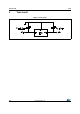
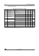
Refer to the test circuits, T
J
= 0 to 125 °C, V
I
= -19 V, I
O
= 500 mA, C
I
= 2.2 µF, C
O
= 1 µF
unless otherwise specified.
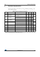
Table 7. Electrical characteristics of L7912AC
Symbol Parameter Test conditions Min. Typ. Max. Unit
V
O
Output voltage T
J
= 25°C -11.75 -12 -12.25 V
V
O
Output voltage
I
O
= -5 mA to -1 A, P
O
≤ 15 W
V
I
= -15.5 to -27 V
-11.5 -12 -12.5 V
ΔV
O
(1)
Line regulation
V
I
= -14.5 to -30 V, T
J
= 25°C 240
mV
V
I
= -16 to -22 V, T
J
= 25°C 120
ΔV
O
(1)
Load regulation
I
O
= 5 mA to 1.5 A, T
J
= 25°C 240
mV
I
O
= 250 to 750 mA, T
J
= 25°C 120
I
d
Quiescent current T
J
= 25°C 3 mA
ΔI
d
Quiescent current change
I
O
= 5 mA to 1 A 0.5
mA
V
I
= -15 to -30 V 1
ΔV
O
/ΔT Output voltage drift I
O
= 5 mA -0.8 mV/°C
eN Output noise voltage B = 10 Hz to 100 kHz, T
J
= 25°C 200 µV
SVR Supply voltage rejection ΔV
I
= 10 V, f = 120 Hz 54 60 dB
V
d
Dropout voltage I
O
= 1 A, T
J
= 25°C, ΔV
O
= 100 mV 1.1 V
I
sc
Short circuit current 1.5 A
I
scp
Short circuit peak current T
J
= 25°C 2.5 A
1. Load and line regulation are specified at constant junction temperature. Changes in V
O
due to heating effects must be
taken into account separately. Pulse testing with low duty cycle is used.