M24C16, M24C08 M24C04, M24C02, M24C01 16Kbit, 8Kbit, 4Kbit, 2Kbit and 1Kbit Serial I²C Bus EEPROM FEATURES SUMMARY ■ ■ ■ ■ ■ ■ ■ ■ ■ ■ ■ Two-Wire I²C Serial Interface Supports 400kHz Protocol Single Supply Voltage: – 2.5 to 5.5V for M24Cxx-W – 1.8 to 5.
M24C16, M24C08, M24C04, M24C02, M24C01 TABLE OF CONTENTS FEATURES SUMMARY . . . . . . . . . . . . . . . . . . . . . . . . . . . . . . . . . . . . . . . . . . . . . . . . . . . . . . . . . . . . . 1 Table 1. Product List . . . . . . . . . . . . . . . . . . . . . . . . . . . . . . . . . . . . . . . . . . . . . . . . . . . . . . . . . . . . 1 Figure 1. Packages . . . . . . . . . . . . . . . . . . . . . . . . . . . . . . . . . . . . . . . . . . . . . . . . . . . . . . . . . . . . . . 1 SUMMARY DESCRIPTION. . .
M24C16, M24C08, M24C04, M24C02, M24C01 INITIAL DELIVERY STATE. . . . . . . . . . . . . . . . . . . . . . . . . . . . . . . . . . . . . . . . . . . . . . . . . . . . . . . . . . 14 MAXIMUM RATING. . . . . . . . . . . . . . . . . . . . . . . . . . . . . . . . . . . . . . . . . . . . . . . . . . . . . . . . . . . . . . . . 15 Table 5. Absolute Maximum Ratings . . . . . . . . . . . . . . . . . . . . . . . . . . . . . . . . . . . . . . . . . . . . . . . 15 DC and AC PARAMETERS . . . . . . . . . . . . . . . . . .
M24C16, M24C08, M24C04, M24C02, M24C01 SUMMARY DESCRIPTION These I²C-compatible electrically erasable programmable memory (EEPROM) devices are organized as 2048/1024/512/256/128 x 8 (M24C16, M24C08, M24C04, M24C02 and M24C01). In order to meet environmental requirements, ST offers these devices in ECOPACK® packages. ECOPACK® packages are Lead-free and RoHS compliant. ECOPACK is an ST trademark. ECOPACK specifications are available at: www.st.com. Figure 2.
M24C16, M24C08, M24C04, M24C02, M24C01 SIGNAL DESCRIPTION Serial Clock (SCL) This input signal is used to strobe all data in and out of the device. In applications where this signal is used by slave devices to synchronize the bus to a slower clock, the bus master must have an open drain output, and a pull-up resistor can be connected from Serial Clock (SCL) to VCC. (Figure 5. indicates how the value of the pull-up resistor can be calculated).
M24C16, M24C08, M24C04, M24C02, M24C01 Figure 5. Maximum RP Value versus Bus Parasitic Capacitance (C) for an I²C Bus VCC Maximum RP value (kΩ) 20 16 RP 12 RP SDA MASTER 8 fc = 100kHz 4 C SCL fc = 400kHz C 0 10 100 1000 C (pF) AI01665b Figure 6.
M24C16, M24C08, M24C04, M24C02, M24C01 Table 3. Device Select Code Device Type Identifier1 Chip Enable2,3 RW b7 b6 b5 b4 b3 b2 b1 b0 M24C01 Select Code 1 0 1 0 E2 E1 E0 RW M24C02 Select Code 1 0 1 0 E2 E1 E0 RW M24C04 Select Code 1 0 1 0 E2 E1 A8 RW M24C08 Select Code 1 0 1 0 E2 A9 A8 RW M24C16 Select Code 1 0 1 0 A10 A9 A8 RW Note: 1. The most significant bit, b7, is sent first. 2.
M24C16, M24C08, M24C04, M24C02, M24C01 DEVICE OPERATION The device supports the I²C protocol. This is summarized in Figure 6.. Any device that sends data on to the bus is defined to be a transmitter, and any device that reads the data to be a receiver. The device that controls the data transfer is known as the bus master, and the other as the slave device. A data transfer can only be initiated by the bus master, which will also provide the serial clock for synchronization.
M24C16, M24C08, M24C04, M24C02, M24C01 Table 4. Operating Modes Mode RW bit WC (1) Bytes 1 X 1 0 X Current Address Read Initial Sequence START, Device Select, RW = 1 START, Device Select, RW = 0, Address Random Address Read 1 1 X reSTART, Device Select, RW = 1 Sequential Read 1 X ≥1 Byte Write 0 VIL 1 START, Device Select, RW = 0 Page Write 0 VIL ≤16 START, Device Select, RW = 0 Similar to Current or Random Address Read Note: 1. X = VIH or VIL. Figure 7.
M24C16, M24C08, M24C04, M24C02, M24C01 Write Operations Page Write Following a Start condition the bus master sends a Device Select Code with the Read/Write bit (RW) reset to 0. The device acknowledges this, as shown in Figure 8., and waits for an address byte. The device responds to the address byte with an acknowledge bit, and then waits for the data byte.
M24C16, M24C08, M24C04, M24C02, M24C01 Figure 8.
M24C16, M24C08, M24C04, M24C02, M24C01 Figure 9.
M24C16, M24C08, M24C04, M24C02, M24C01 Figure 10.
M24C16, M24C08, M24C04, M24C02, M24C01 tion, as shown in Figure 10., without acknowledging the byte. and the device continues to output data from memory address 00h. Sequential Read Acknowledge in Read Mode This operation can be used after a Current Address Read or a Random Address Read. The bus master does acknowledge the data byte output, and sends additional clock pulses so that the device continues to output the next byte in sequence.
M24C16, M24C08, M24C04, M24C02, M24C01 MAXIMUM RATING Stressing the device outside the ratings listed in Table 5. may cause permanent damage to the device. These are stress ratings only, and operation of the device at these, or any other conditions outside those indicated in the Operating sections of this specification, is not implied. Exposure to Absolute Maximum Rating conditions for extended periods may affect device reliability.
M24C16, M24C08, M24C04, M24C02, M24C01 DC AND AC PARAMETERS This section summarizes the operating and measurement conditions, and the DC and AC characteristics of the device. The parameters in the DC and AC Characteristic tables that follow are derived from tests performed under the Measure- ment Conditions summarized in the relevant tables. Designers should check that the operating conditions in their circuit match the measurement conditions when relying on the quoted parameters. Table 6.
M24C16, M24C08, M24C04, M24C02, M24C01 Table 9. DC Characteristics (M24Cxx-W, Device Grade 3) Symbol Test Condition (in addition to those in Table 6.) Parameter Min. Max. Unit VIN = VSS or VCC ±2 µA VOUT = VSS or VCC, SDA in Hi-Z ±2 µA VCC=5V, fC=400kHz (rise/fall time < 30ns) 3 mA VCC =2.5V, fC=400kHz (rise/fall time < 30ns) 3 mA VIN = VSS or VCC, VCC = 5 V 5 µA VIN = VSS or VCC, VCC = 2.
M24C16, M24C08, M24C04, M24C02, M24C01 Figure 11. AC Measurement I/O Waveform Input Levels Input and Output Timing Reference Levels 0.8VCC 0.7VCC 0.3VCC 0.2VCC AI00825B Table 12. Input Parameters Symbol Parameter1,2 Test Condition Min. Unit CIN Input Capacitance (SDA) 8 pF CIN Input Capacitance (other pins) 6 pF 70 kΩ ZWCL WC Input Impedance VIN < 0.3 V 15 ZWCH WC Input Impedance VIN > 0.7VCC 500 Pulse width ignored (Input Filter on SCL and SDA) Single glitch tNS Note: 1.
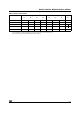
M24C16, M24C08, M24C04, M24C02, M24C01 Table 13. AC Characteristics (M24Cxx-W) Test conditions specified in Table 6. and Table 11. Symbol Alt. Parameter Min. Max.
M24C16, M24C08, M24C04, M24C02, M24C01 Figure 12.
M24C16, M24C08, M24C04, M24C02, M24C01 PACKAGE MECHANICAL Figure 13. PDIP8 – 8 pin Plastic DIP, 0.25mm lead frame, Package Outline E b2 A2 A1 b A L c e eA eB D 8 E1 1 PDIP-B Note: Drawing is not to scale. Table 15. PDIP8 – 8 pin Plastic DIP, 0.25mm lead frame, Package Mechanical Data millimeters inches Symbol Typ. Min. A Max. Typ. Min. 5.33 A1 Max. 0.210 0.38 0.015 A2 3.30 2.92 4.95 0.130 0.115 0.195 b 0.46 0.36 0.56 0.018 0.014 0.022 b2 1.52 1.14 1.78 0.060 0.
M24C16, M24C08, M24C04, M24C02, M24C01 Figure 14. SO8 narrow – 8 lead Plastic Small Outline, 150 mils body width, Package Outline h x 45˚ A2 A C B ddd e D 8 E H 1 A1 α L SO-A Note: 1. Drawing is not to scale. 2. The ‘1’ that appears in the top view of the package shows the position of pin 1 and the ‘N’ indicates the total number of pins. Table 16. SO8 narrow – 8 lead Plastic Small Outline, 150 mils body width, Package Mechanical Data millimeters inches Symbol Typ Min Max A 1.
M24C16, M24C08, M24C04, M24C02, M24C01 Figure 15. UFDFPN8 (MLP8) 8-lead Ultra thin Fine pitch Dual Flat Package No lead 2x3mm², Outline e D b L1 L3 E E2 L A D2 ddd A1 UFDFPN-01 Note: 1. Drawing is not to scale. 2. The central pad (the area E2 by D2 in the above illustration) is pulled, internally, to VSS. It must not be allowed to be connected to any other voltage or signal line on the PCB, for example during the soldering process. 3.
M24C16, M24C08, M24C04, M24C02, M24C01 Figure 16. TSSOP8 – 8 lead Thin Shrink Small Outline, Package Outline D 8 5 c E1 1 E 4 α A1 A L A2 L1 CP b e TSSOP8AM Note: 1. Drawing is not to scale. 2. The circle in the top view of the package indicates the position of pin 1. Table 18. TSSOP8 – 8 lead Thin Shrink Small Outline, Package Mechanical Data millimeters inches Symbol Typ. Min. A 0.050 0.150 0.800 1.050 b 0.190 c 0.090 A2 Typ. Min. 1.200 A1 1.000 CP Max. 0.0472 0.0020 0.
M24C16, M24C08, M24C04, M24C02, M24C01 Figure 17. TSSOP8 3x3mm² – 8 lead Thin Shrink Small Outline, 3x3mm² body size, Package Outline D 8 5 c E1 1 E 4 α L A1 A A2 L1 CP b e TSSOP8BM Note: 1. Drawing is not to scale. 2. The circle in the top view of the package indicates the position of pin 1. Table 19. TSSOP8 3x3mm² – 8 lead Thin Shrink Small Outline, 3x3mm² body size, Mechanical Data millimeters inches Symbol Typ. Min. A Max. Min. 1.100 A1 0.050 0.150 0.750 0.950 b 0.
M24C16, M24C08, M24C04, M24C02, M24C01 PART NUMBERING Table 20. Ordering Information Scheme Example: M24C16 – W DW 3 T P /W Device Type M24 = I2C serial access EEPROM Device Function 16 = 16 Kbit (2048 x 8) 08 = 8 Kbit (1024 x 8) 04 = 4 Kbit (512 x 8) 02 = 2 Kbit (256 x 8) 01 = 1 Kbit (128 x 8) Operating Voltage W = VCC = 2.5 to 5.5V (400 kHz) R = VCC = 1.8 to 5.
M24C16, M24C08, M24C04, M24C02, M24C01 REVISION HISTORY Table 21. Document Revision History Date Version 10-Dec-1999 2.4 TSSOP8 Turned-Die package removed (p 2 and order information) Lead temperature added for TSSOP8 in table 2 18-Apr-2000 2.5 Labelling change to Fig-2D, correction of values for ‘E’ and main caption for Tab-13 05-May-2000 2.6 Extra labelling to Fig-2D 23-Nov-2000 3.
M24C16, M24C08, M24C04, M24C02, M24C01 Information furnished is believed to be accurate and reliable. However, STMicroelectronics assumes no responsibility for the consequences of use of such information nor for any infringement of patents or other rights of third parties which may result from its use. No license is granted by implication or otherwise under any patent or patent rights of STMicroelectronics. Specifications mentioned in this publication are subject to change without notice.