
Product Card

6.2 Clocks
Two clocks are available on STM32MP157x-EV1 for STM32MP157xAA3 target microcontroller.
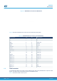
6.2.1 LSE clock
• External 32.768 kHz crystal
6.2.2 HSE clock
• External 24 MHz crystal
6.3 Reset sources
The reset signal of the STM32MP157x-EV1 platform is active low.
Sources of the platform reset are:
•
Two reset buttons MB1263/B1 and MB1262/B2 (BLACK buttons)
• STM32MP157xAA3: internal voltage monitor, SW request or Watchdog
• STPMIC1
• JTAG/SWD connector MB1262/CN14
• ETM Trace Mictor-38 connector MB1262/U10
• Embedded ST-LINK/V2-1
The STM32MP157xAA3 also drives a sub system reset, SUB_NRST signal on PD10 IO, to the peripherals: USB
Host Hub, MFX, Ethernet, and RGB_LTDC connector.
6.4 User buttons and LEDs
The T
able 7 describes the HW configuration for the user buttons and LEDs
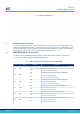
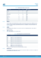
Table 7. HW configuration for the user buttons and LEDs
IO LED color and label Button label
PD8 PD8 is connected to the ORANGE LD4. Active High -
PD9 PD9 is connected to the BLUE LD5. Active High -
PA13 PA13 is connected to RED LD2. Active Low User PA13
PA14 MFX_IO13 is connected to ORANGE LED LD7. Active Low User PA14
6.5 Physical input devices: buttons
The STM32MP157x-EV1 board provides a number of input devices for physical human control.
These are:
•
Two Reset buttons (MB1263/B1 and MB1262/B2)
• Four-way joystick controller with select key (MB1262/B1)
• Wake-up button (MB1263/B4)
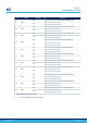
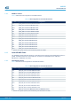
Table 8. Physical user devices: buttons
Devices Purpose/IO
Wakeup button (MB1263/B4)
Awakes the platform from low-power modes.
Connected to STPMIC1A PONKEY, which
generates a wake-up signal on STM32MP1 PA0
Reset buttons (MB1263/B1 or MB1262/B2) NRST signal
JOY_CENTER: Joystick select key (MB1262/B1 pin2) MFX_IO0
JOY_DOWN: Joystick down direction (MB1262/B1 pin3) MFX_IO1
UM2535
Clocks
UM2535 - Rev 2
page 13/59