
User's Manual
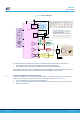
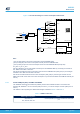
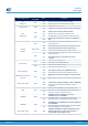
Table Of Contents
- 1 Features
- 2 Ordering information
- 3 Development environment
- 4 Conventions
- 5 Quick start
- 8 STM32WL Nucleo-64 board information
- Appendix A STM32WL Nucleo-64 I/O assignment
- Appendix B Federal Communications Commission (FCC) and Innovation, Science and Economic Development Canada (ISED) Compliance Statements
- Appendix C Déclaration de conformité CE simplifiée
- Revision history
- Contents
- List of tables
- List of figures

Figure 18. RF block diagram
Power
management
Reg PA
PA HP
PA LP
Rx
RF
antenna
matching
Rx
matching
Tx HP
matching
Tx LP
matching
VFBSMPS
VLXSMPS
VDDSMPS
VDDRF
VDD_RF
VDDRF1V55
VDDPA
VR_PA
RFO_HP
RFO_LP
RFI_P
RFI_N
FE_CTRL1
FE_CTRL1
FE_CTRL2
FE_CTRL3
TCXO
PB0-VDD_TCXO
OSC_IN
OSC_OUT
Xtal
RFO_HP
RFO_LP
Rx
matching
RFI_P
RFI_N
RF
antenna
matching
RF Rx path
RF Tx LP path
RF Tx HP path
TCXO
PB0-VDD_TCXO
OSC_IN
OSC_OUT
Xtal
32MHz HSE
VFBSMPS
VLXSMPS
SMPS part
STM32 WL transceiver
DC
switch
DC
switch
SP3T
RF antenna matching
The screwed and glue-fixed antennas to connect on the SMA connector and provided in the blister are:
• ANT-SS900 from LPRS company for NUCLEO-WL55JC1 (high band frequency)
• ANT-SS450-510 from LPRS company for NUCLEO-WL55JC2 (low band frequency)
Those antennas have been used for the different FCC/ISED/CE certifications. It is then mandatory to use those
referenced antennas (and only those) for radiated tests on the STM32WL Nucleo-64 boards.
6.6.4 Current consumption measurement (I_SoC)
Jumper JP1, labeled I_SoC, is used to measure the STM32WL microcontroller consumption by removing the
jumper and by connecting an ammeter. Their location in the power structure is shown in Figure 19.
1. JP1 ON. STM32WL is powered with 3V3 voltage (default)
2. JP4 OFF. An ammeter must be connected to measure the STM32WL current. If there is no ammeter, the
STM32 is not powered.
UM2592
Board functions
UM2592 - Rev 1
page 27/49