
User's Manual
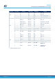
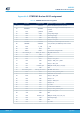
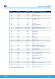
Table Of Contents
- 1 Features
- 2 Ordering information
- 3 Development environment
- 4 Conventions
- 5 Quick start
- 8 STM32WL Nucleo-64 board information
- Appendix A STM32WL Nucleo-64 I/O assignment
- Appendix B Federal Communications Commission (FCC) and Innovation, Science and Economic Development Canada (ISED) Compliance Statements
- Appendix C Déclaration de conformité CE simplifiée
- Revision history
- Contents
- List of tables
- List of figures

Solder bridge control
Solder
bridge (SB)
State
(1)
Description
(1)
VDDA / VREF+ supply SB24
OFF
STM32WL VDDA/VREF+ disconnected from VDD_SYS. So
STM32WL VDDA/VREF+ must be supplied externally by
A
VDD.
IOREF and 3V3 connection SB25
ON
IOREF connected to the 3V3 power supply. Be careful to
remove SB29 to avoid voltage supply conflict with VDD_MCU.
OFF IOREF not connected to 3V3 power supply
VDDA / VREF+ supply SB26
ON
STM32WL VDDA/VREF+ supplied externally by AVDD (so
SB24 must not be fitted to avoid supply conflict)
OFF
STM32WL VDDA/VREF+ disconnected from AVDD. So SB24
must be fitted to supply properly STM32WL VDDA/VREF+
pins.
I_SYS current probing SB27
ON VDD_SYS generated from VDD_MCU
OFF For I_SYS current probing on JP5 jumper
I_RF current probing SB28
ON VDD_RF generated from VDD_MCU
OFF For I_RF current probing on JP2 jumper
IOREF and VDD_MCU
connection
SB29
ON
IOREF connected to the VDD_MCU power supply. Be
careful to remove SB25 to avoid voltage supply conflict
with 3V3
OFF IOREF not connected to VDD_MCU power supply
PB0 on ST morpho connector SB30
ON PB0 connected to ST morpho connector (CN10 pin 22)
OFF PB0 not connected to ST morpho connector
PB3 on morpho SB31
ON PB3 connected to Arduino™ D3
OFF PB3 not connected to Arduino™ D3
I_APP current probing SB32
ON RF front-end supply VDD_APP generated from VDD_MCU
OFF For I_APP current probing on JP9 jumper
1.
The default SB state is in bold.
UM2592
Solder bridges
UM2592 - Rev 1
page 31/49