
User's Manual
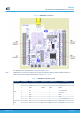
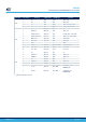
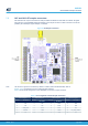
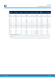
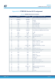
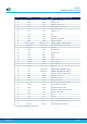
Table Of Contents
- 1 Features
- 2 Ordering information
- 3 Development environment
- 4 Conventions
- 5 Quick start
- 8 STM32WL Nucleo-64 board information
- Appendix A STM32WL Nucleo-64 I/O assignment
- Appendix B Federal Communications Commission (FCC) and Innovation, Science and Economic Development Canada (ISED) Compliance Statements
- Appendix C Déclaration de conformité CE simplifiée
- Revision history
- Contents
- List of tables
- List of figures

Figure 23. ARDUINO
®
connectors
The related pinout for the ARDUINO
®
connector is listed in Table 17.
Note:
ARDUINO
®
Uno V3 D0 and D1 signals are connected by default on USART1 (MCU I/O PB6 and PB7). For
details about how to modify the UART interface, refer to Section 6.6.5 .
Table 17. ARDUINO
®
connectors pinout
Connector Pin number Pin name Signal name
STM32 pin
(1)
Function
(1)
CN6
1 NC - - Reserved for test
2 IOREF - - I/O reference
3 NRST T_NRST NRST RESET
4 3V3 - - 3.3 V input/output
5 5V - - 5 V output
6 GND - - GND
7 GND - - GND
8 VIN - - 7 V - 12 V input power
CN8
1 A0 ADC PB1 ADC1_IN5
2 A1 ADC PB2 ADC1_IN4
UM2592
CN5, CN6, CN8, and CN9 ARDUINO® Uno V3 connectors
UM2592 - Rev 1
page 34/49