
User's Manual
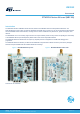
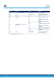
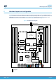
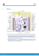
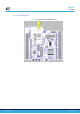
Table Of Contents
- 1 Features
- 2 Ordering information
- 3 Development environment
- 4 Conventions
- 5 Quick start
- 8 STM32WL Nucleo-64 board information
- Appendix A STM32WL Nucleo-64 I/O assignment
- Appendix B Federal Communications Commission (FCC) and Innovation, Science and Economic Development Canada (ISED) Compliance Statements
- Appendix C Déclaration de conformité CE simplifiée
- Revision history
- Contents
- List of tables
- List of figures

5 Quick start
The STM32WL Nucleo-64 board is an easy-to-use and low-cost development kit used to evaluate and start
development quickly with an
STM32WL Series microcontroller in the UFBGA73 package. Before installing and
using the product, accept the Evaluation Product License Agreement from the www.st.com/epla webpage. For
more information on the STM32WL Nucleo-64 and demonstration software, visit the www.st.com/stm32nucleo
webpage.
5.1 Getting started
Follow the sequence below to configure the STM32WL Nucleo-64 board and launch the demonstration
application (refer to Figure 4 for component location):
1. Check jumper positions on board, JP1 (I_SoC) ON, JP3 (BOOT0) ON, JP4 (Power source) on
5V_USB_STLK, JP7 (5V_PWR) ON, and JP8 all 6 jumpers ON
The jumper position on the board is explained in Table 4
2. Connect the STM32WL Nucleo-64 board to a PC with a standard USB cable through the CN1 USB
connector to power the board. Then the LED5 (PWR) green LED and the LED6 (COM) LED light up, the
three LED1, LED2, and LED3 LEDs blink.
3. On the PC, connect a UART terminal to the board using the following settings:
– UART terminal: new line received = auto; new line transmit = LF (line feed)
– Serial port setting: select COM port number, 9600 baud rate, 8-bit data, parity none, 1 stop bit, no flow
control
4. Press on the B4 Reset button of the STM32WL Nucleo-64 board.
– The STM32WL Nucleo-64 board remains silent until it gets a command from the connected PC to start
sending beacon on one of the beacon frequencies.
– The frequency is selected depending on the region.
– After the version check, the first three commands to send to the PC must set region, subregion, and
start the beacon (AT+REGION=x and AT_BEACON_ON). The first two commands select the format of
the transmission beacon. The third command starts sending the beacon.
– For a list of available regions run AT_LIST_REGIONS.
5. Then the concentrator (a second NUCLEO-WL55JC) starts flashing green LED on each time slot of the
network.
6. To get the demonstration fully up and running, up to 14 Nucleo demonstration sensors can be flashed and
placed against a Nucleo demonstration concentrator.
7. This demo application software is available on the www.st.com website.
Table 4. Jumper configuration
Jumper Definition
Position
(1)
Comment
(1)
JP1 I_SoC ON
For STM32WL current
measurements
JP2 I_RF OFF (SB28 ON)
For STM32WL current
measurements (RF part)
JP3 BOOT0 ON
Allows to disconnect PH3/
BOOT0 pull-down resistor and to
use it as an I/O if the software
BOOT0 is used, thanks to the
option bytes.
JP4 5 V power-source selection
[1-2] (Default) 5V_USB_STLK (from ST-LINK)
[3-4] (optional) 5V_VIN
[5-6] (optional) E5V
[7-8] (optional) 5V_USB_CHGR
UM2592
Quick start
UM2592 - Rev 1
page 6/49