
User's Manual
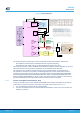
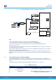
Table Of Contents
- 1 Features
- 2 Ordering information
- 3 Development environment
- 4 Conventions
- 5 Quick start
- 8 NUCLEO-WL55JC board information
- Appendix A STM32WL Nucleo-64 I/O assignment
- Appendix B Federal Communications Commission (FCC) and Innovation, Science and Economic Development Canada (ISED) Compliance Statements
- Appendix C Déclaration de conformité CE simplifiée
- Revision history
- Contents
- List of tables
- List of figures

To properly isolate the MCU STM32 WL from the STLINK-V3E debugger, it is recommended to remove the
following jumpers: the 6 jumpers of JP8 and the jumper of JP7. In this case, there is no current leakage coming
from the STLINK-V3E debugger in
STM32WL current consumptions.
6.4.1 Debugging while using VIN or EXT as an external power supply
When powered by VIN or E5V, it is still possible to use the ST-LINK for programming or debugging, but it is
mandatory to power the board first using VIN or EXT
, then to connect the USB cable to the PC. In this way, the
enumeration succeeds, thanks to the external power source.
The following power-sequence procedure must be respected:
1. Connect jumper JP4 between pins 5 and 6 for E5V or between pins 3 and 4 for VIN,
2. Connect the external power source to VIN or E5V,
3. Power on the external power supply 7 V < VIN < 12 V for VIN, or 5 V for E5V,
4. Check that the LED5 green LED is turned ON,
5. Connect the PC to the CN1 USB connector.
If this order is not respected, the board may be powered by USB first, then by VIN or E5V as the following risks
may be encountered:
1. If more than 300 mA current is needed by the board, the PC may be damaged or the current supplied can be
limited by the PC. As a consequence, the board is not powered correctly.
2. 300 mA is requested at enumeration so there is a risk that the request is rejected and the enumeration does
not succeed if the PC cannot provide such current. Consequently, the board is not power supplied and LED5
remains OFF.
6.5 Clock sources
6.5.1 HSE clock (high-speed external clock)
There are two ways to configure the pins corresponding to the high-speed external clock (HSE):
• HSE on-board oscillator from X3 crystal: For typical frequencies, capacitors, and resistors, refer to the
STM32 microcontroller datasheet and the application note Oscillator design guide for STM8AF/AL/S, STM32
MCUs and MPUs (AN2867) for the oscillator design guide. The X3 crystal has the following characteristics:
32 MHz, 10 pF load capacitance, 10 ppm. It is recommended to use NDK_NX2016SA 32MHz EXS00A-
CS06465 manufactured by NDK. The configuration must be:
–
X3 crystal (and X4 TCXO) soldered
– No C30 and no C38 as those capacitors are integrated into the STM32WL MCU
– SB20 OFF in order not to supply the TCXO
– C31 OFF in order not to have a 32 MHz signal coming from the TCXO
– R39 and R40 ON to connect the X3 crystal to the STM32WL55 MCU
• HSE on-board oscillator from X4 TCXO (Default configuration): The X4 TCXO has the following
characteristics: 32MHz, 10pF load capacitance. It is recommended to use NT2016SF-32M-END5875A
manufactured by NDK. The configuration must be:
– X4 TCXO (and X3 crystal) soldered
– SB20 ON to supply the TCXO
– 10 pF C31 and 220 Ω R2 ON to have a 32 MHz signal coming from the TCXO
– R39 and R40 OFF to isolate the X3 crystal from the STM32WL55 MCU
Note: Whatever the configuration is (X3 crystal or X4 TCXO), both X3 crystal and X4 TCXO are assembled on the
board to avoid to solder or desolder either X3 or X4 to choose between X3 crystal and X4 TCXO configuration.
UM2592
Clock sources
UM2592 - Rev 2
page 24/50