
User's Manual
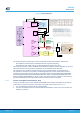
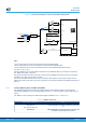
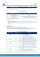
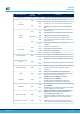
Table Of Contents
- 1 Features
- 2 Ordering information
- 3 Development environment
- 4 Conventions
- 5 Quick start
- 8 NUCLEO-WL55JC board information
- Appendix A STM32WL Nucleo-64 I/O assignment
- Appendix B Federal Communications Commission (FCC) and Innovation, Science and Economic Development Canada (ISED) Compliance Statements
- Appendix C Déclaration de conformité CE simplifiée
- Revision history
- Contents
- List of tables
- List of figures

6.5.2 LSE clock (low-speed external clock) – 32.768 kHz
There are three ways to configure the pins corresponding to the low-speed clock (LSE):
• On-board oscillator (Default): X2 crystal. Refer to the application note Oscillator design guide
for STM8AF/AL/S, STM32 MCUs and MPUs (AN2867) as the oscillator design guide for STM32
microcontrollers. It is recommended to use NX3215SA-32.768kHz-EXS00A-MU00527 (32.768 kHz, 6 pF
load capacitance, 20 ppm) from NDK.
–
SB11 and SB14 OFF
– SB12 and SB13 ON
• Oscillator from external PC14: from external oscillator through the pin 25 of CN7 connector. The
configuration must be:
– SB11 (and SB14 ON, but not necessary)
– SB12 and SB13 OFF
• LSE not used: PC14 and PC15 are used as GPIOs instead of the low-speed clock. The configuration must
be:
– SB11 and SB14 ON (to get them on CN7)
– SB12 and SB13 OFF
6.6 Board functions
6.6.1 LEDs
LED1 user LED
This blue LED is a user LED connected to STM32WL I/O PB15. T
o light the LED LED1, a HIGH logic state must
be written in the corresponding GPIO PB15.
LED2 user LED
This green LED is a user LED connected to STM32WL I/O PB9. To light the LED LED2, a HIGH logic state must
be written in the corresponding GPIO PB9.
LED3 user LED
This red LED is a user LED connected to STM32WL I/O PB11. To light the LED LED3, a HIGH logic state must be
written in the corresponding GPIO PB11.
LED4 USB power fault (OC, overcurrent)
LED4 indicates that the board power consumption on USB ST-LINK exceeds 500 mA, consequently, the user
must check the root cause of the overconsumption or power the board using an external power supply.
LED5 (5V_PWR)
The green LED indicates that the STM32WL part is powered and +5 V power is available on CN6 pin 5 and CN7
pin 18 if the jumper JP7 is ON.
LED6 (STLINK-V3 COM LED)
The bicolor LED LED6 (green, red) provides information about STLINK-V3E communication status. LED6
indicates the communication progress between the PC and the STLINK-V3E, with the following setup:
• Blinking red: the first USB enumeration with the PC is taking place
• Red LED ON: when the initialization between the PC and STLINK-V3E is complete
• Blinking red or green: during programming and debugging with target
• Green LED ON: communication finished and successful
• Orange ON: communication failure
UM2592
Board functions
UM2592 - Rev 2
page 25/50