
User's Manual
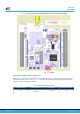
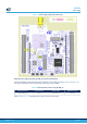
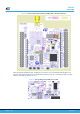
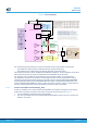
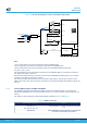
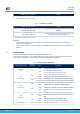
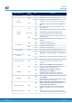
Table Of Contents
- 1 Features
- 2 Ordering information
- 3 Development environment
- 4 Conventions
- 5 Quick start
- 8 NUCLEO-WL55JC board information
- Appendix A STM32WL Nucleo-64 I/O assignment
- Appendix B Federal Communications Commission (FCC) and Innovation, Science and Economic Development Canada (ISED) Compliance Statements
- Appendix C Déclaration de conformité CE simplifiée
- Revision history
- Contents
- List of tables
- List of figures

Solder bridge configuration
(1)
Feature
(1)
SB6, SB10, SB2, SB4: OFF
1.
The default configuration is shown in bold
Table 12. LPUART1 connection
Solder bridge configuration
(1)
Feature
(1)
SB3, SB5: ON
SB2, SB4, SB6, SB10: OFF
LPUART1 (PA2/PA3) connected to STLINK-V3E Virtual
COM port.
SB2, SB4: ON
SB3, SB5, SB7, SB9: OFF
LPUART1 (PA2/PA3) connected to ARDUINO
®
(D1 & D0) and
ST morpho connector (CN10 pin 35 and 37).
1. The default configuration is shown in bold
By default:
• Communication between the target STM32WL and the STLINK-V3E MCU is enabled on LPUART1 to
support the Virtual COM port.
• Communication between the target STM32WL and ARDUINO
®
(and ST morpho) connectors is enabled on
USART1.
6.7 Solder bridges
All the 31 solder bridges are located on the STM32WL Nucleo-64 board.
All the solder bridges present on the
STM32WL Nucleo-64 board are used to configure several I/Os and power
supply pins for compatibility of features and pinout with the target STM32WL supported.
Table 13. Solder bridge configuration
Solder bridge control
Solder
bridge (SB)
State
(1)
Description
(1)
3.3 V LDO
output
SB1
ON U2 LDO output provides 3.3 V
OFF
U2 LDO output does NOT provide 3.3 V.
The user must connect an external 3V3 source.
PA2
LPUAR
T1 TX
SB2
ON ARD_D1_TX connected to LPUART1 TX PA2
OFF ARD_D1_TX not connected to LPUART1 TX PA2
SB3
ON STLINK_TX (T_VCP_TX) connected to LPUART1 TX PA2
OFF STLINK_TX (T_VCP_TX) not connected to LPUART1 TX PA2
PA3
LPUAR
T1 RX
SB4
ON ARD_D0_RX connected to LPUART1 RX PA3
OFF ARD_D0_RX not connected to LPUART1 RX PA3
SB5
ON STLINK_RX (T_VCP_RX) connected to LPUART1 RX PA3
OFF
STLINK_RX (T_VCP_RX) not connected to LPUART1 RX
P
A3
PB6
USAR
T1 TX
SB6
ON STLINK_TX (T_VCP_TX) connected to USART1 TX PB6
OFF
STLINK_TX (T_VCP_TX) not connected to USART1 TX
PB6
SB7
ON ARD_D1_TX connected to USART1 TX PB6
OFF ARD_D1_TX not connected to USART1 TX PB6
T_SWO on PB3 SB8
ON T_SWO connected to PB3
UM2592
Solder bridges
UM2592 - Rev 2
page 29/50